58 | City Series CV40E-12
installation-power vent
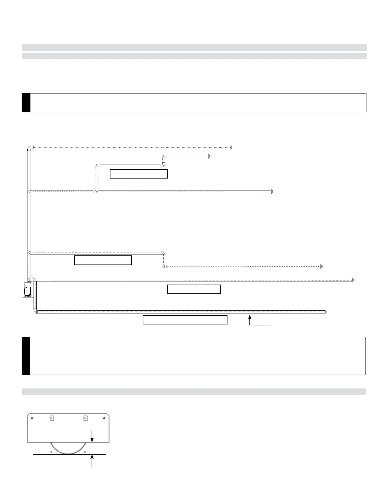
Vent Chart for Power Vent Only
Horizontal Terminations - End of Line Horizontal Vent Chart
Vent Restrictor Position (End of Line)
This negative run is for the end of
line power vent cap only. Do not
run with the inline power vent.
72' (21.95 m) overall length max.
Shown with 5 - 90
0
elbows
72' (21.95 m) overall length max.
Shown with 3 - 90
0
elbows
72' (21.95 m) run (no rise)
Shown with 2 elbows (negative run 72' - 21.95 m)
The gas power vent system is designed to allow the installation of a gas appliance when typical vent congurations (shown in this manual) are not
possible.
NOTES
• • Rigid pipe is approved for up to 72 feet (22 m).Rigid pipe is approved for up to 72 feet (22 m).
• • Flex pipe is approvedFlex pipe is approved for up to 40 feet (12.2 m) using two 20 foot (6.1 m) ex kits (part # 946-756). for up to 40 feet (12.2 m) using two 20 foot (6.1 m) ex kits (part # 946-756).
RIGID PIPE: MUST USE RIGID PIPE ADAPTOR (PART # 510-994).
For the complete Power Vent installation, refer the Power Vent System installation instruction in Power vent system Kit
End Line Power Vent Kit # 946-535
1" (25mm)
IMPORTANT
• • Maximum total vent length (based on overall length of combined chimney components) = 72' (21.95 m) Maximum total vent length (based on overall length of combined chimney components) = 72' (21.95 m)
• • Maximum total negative vent length = 7' (2.1 m). Maximum total negative vent length = 7' (2.1 m).
• • Do not run positive venting after a negative run.Do not run positive venting after a negative run.
• • Maximum of six - 90° elbows permitted. Maximum of six - 90° elbows permitted.
• • One 90° elbow = two 45° elbows.One 90° elbow = two 45° elbows.
• • Minimum 4' (1.2 m) from the unit prior to terminating.Minimum 4' (1.2 m) from the unit prior to terminating.