City Series CV40E-12 | 49
installation
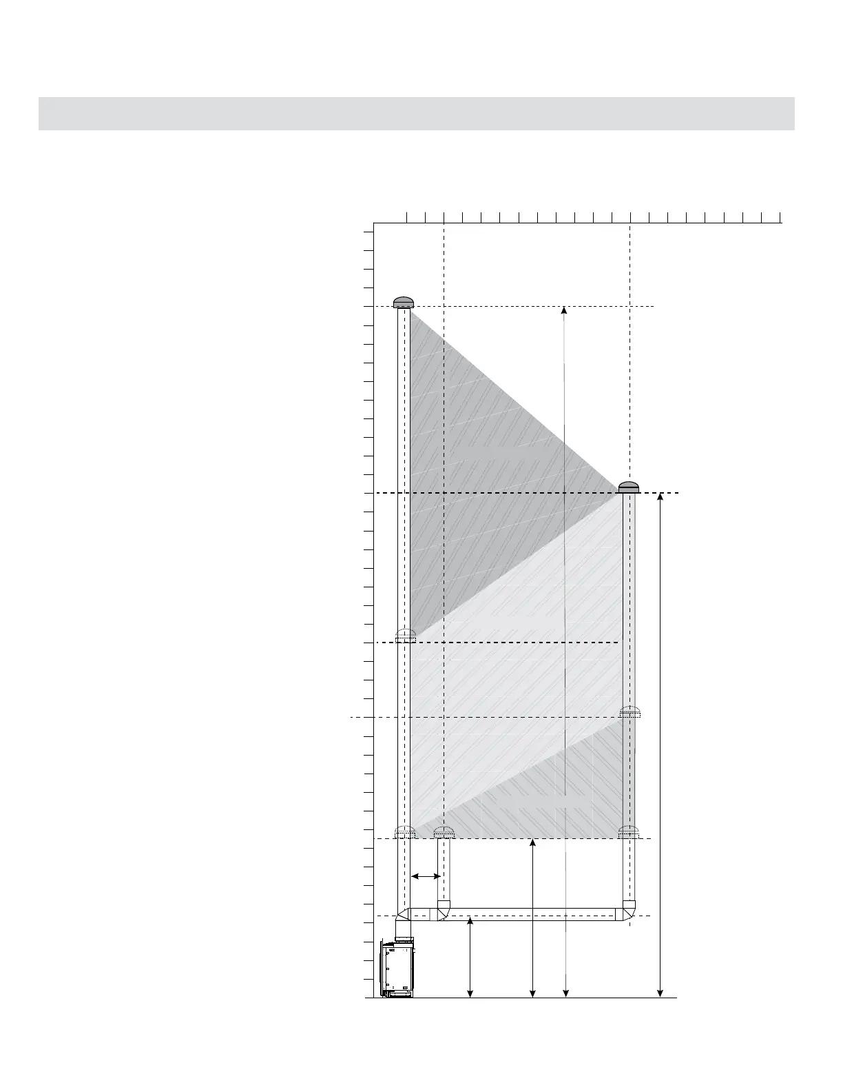
Venting Arrangement for Vertical Terminations - Straight Vertical Venting and/or with a Max. of
Two (2) 90
o
Elbows (1 - 90
o
= 2 - 45
o
)
The shaded area in the diagram shows all allowable combinations
of straight vertical and oset to vertical terminations, using two
90
o
elbows, with Rigid Pipe Venting Systems.
Two 45
o
elbows equal to one 90
o
elbow.
• Vent must be supported at osets.
• Minimum distance between elbows is 1 ft. (305mm).
• Maintain clearances to combustibles as listed in the
"Clearances" section.
• Horizontal vent must be supported every 3 feet.
• Firestops are required at each oor level and whenever
passing through a wall.
• Must use optional rigid pipe adaptor (Part# 510-994) when
using rigid pipe vent systems.
• Refer to the "Vent Restrictor Position" section for details on
how to change the vent restrictor from the factory setting
of Set 0 through to Set 3 if required.
Maximum: 37 ft. (11.2m)
Minimum
8’6” (2.6m)
Min. 56-1/4”
(1429mm)
*Minimum length of pipe
between elbows 12” (305mm)
Maximum: 27 ft. (8.2m)
0
2
4
6
4
0
8
1
0
1
2
1
4
1
6
1
8
2
0
2
2
2
4
2
6
2
8
3
0
Vertical Height (Feet)
3
2
3
4
3
6
3
8
6
8
Horizontal (Feet)
2
0
4
1
0
1
2
1
6
1
8
1
4
2
Vent Restrictor on Set 2
Vent Restrictor on Set 3
Vent Restrictor on Set 1
*