4
ADT and ADT View user guide
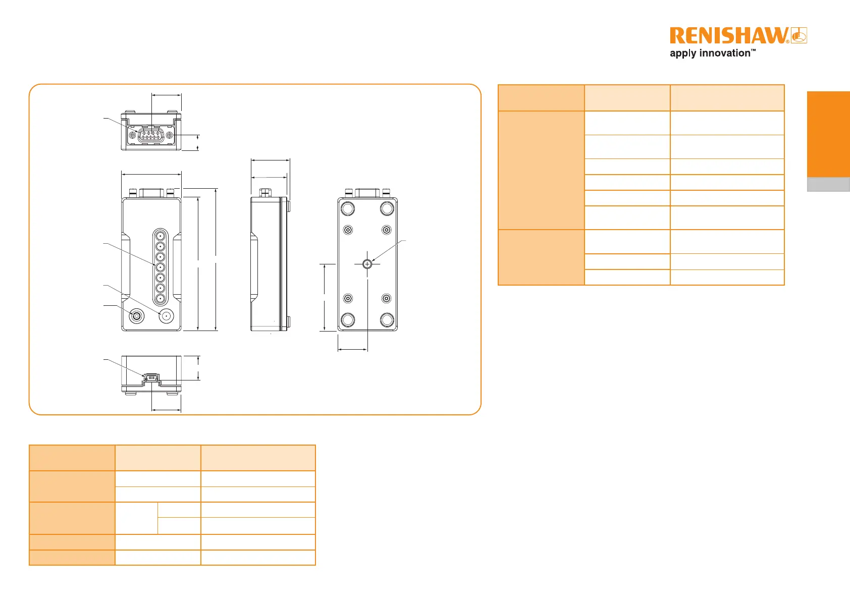
1.5 ADTa-100 dimensions 1.7 ADTa-100 LED indication
LED Indication Status
Signal strength
indicator
7 Blue LEDs
Excellentsignalstrength
(RESOLUTE systems only)
7 Green LEDs
Excellentsignalstrength
(EVOLUTE systems only)
4 to 6 Green LEDs Good signal strength
2 to 3 Orange LEDs Moderate signal strength
1 Red LED Poor signal
Flashing LEDs
Connected readhead is in a
position error state
Status
Green LED
Connected encoder is in
diagnostic mode
Orange LED Idle
Red LED Connection error
1.8 ADTa-100 user button
• TousetheADTa-100instandalonemodebrieypresstheuserbutton
(~0.5 second). This will command the encoder to enter diagnostic mode.
• Toclearlatchederrors,brieypresstheuserbutton(0.5second).
Providedthesourceoftheerrorisnolongerpresent,theashingofthe
signal strength LEDs will stop and normal operation will resume.
• To turn off the connected encoder and leave diagnostic mode, press the
userbutton(>3seconds)
20
90
9.8
96
40
26.4
24.4
20
45
20
16.8
Signal strength
LEDs(x7)
Status LED
User button
Mini-B USB socket
M6 accessory
mounting thread -
maximumpermissible
screw protrusion into
body 10 mm
1.6 ADTa-100 pin-out
Function Signal
Input pins
(9-way D-type socket)
Power
5 V 4, 5
0 V 8, 9
Serial
communications
REQ/SD
+ 2
- 3
Shield (case) Outer Cable screen
Not Connected – 1, 6, 7
9-way D-type
socket
 Loading...