repligen.com XC-LAB-UG-V4
A dedicated tablet running the XCell™ Lab software operates each controller
• Each controller supports up to 2 XCell ATF® Devices, depending on the model purchased
• The XCell™ Lab Controller will run XCell ATF® 1, 2 and 4 Devices, with adjustment of A2C
tubing, A2B tubing and flow sensor
• Two XCell ATF® Devices from a single controller may be connected to two bioreactors.
Alternatively, two XCell ATF® Devices from a single controller may be connected to a single
bioreactor for an increased rate of media exchange.
6.5 XCell™ Lab Controller
XCell™ Lab Controller is available in 3 different models (Table 4
). Controller model number XC-LAB-
D-P utilizes a permeate pressure sensor to gain insight into real-time filter performance and fouling
characteristics. This data helps determine when a filter should be replaced and improves scale-up
prediction.
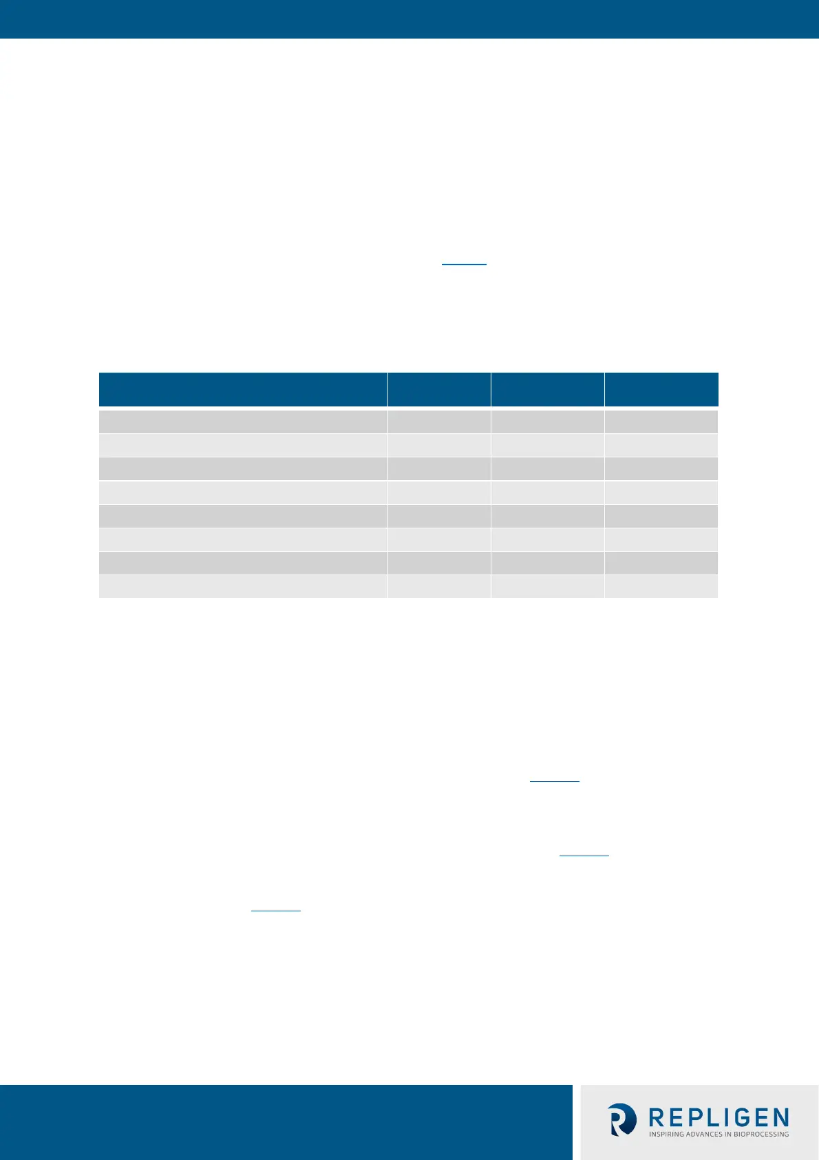
Table 4. XCell™ Lab Controller model comparison
Features XC-LAB-S XC-LAB-D XC-LAB-D-P
Single ATF Operation
Dual ATF Operation ×
In/Out of Phase or Independent Dual Operation N/A
Transmembrane Pressure (P3) × ×
Single Use XCell ATF® 1
Single Use XCell ATF® 2
Autoclavable XCell ATF® 2
Autoclavable XCell ATF® 4
If monitoring filter fouling and permeate pressure is important to your process, then you should
consider purchasing the D-P model as this feature is not available on the S and D models. If you
purchase an S model, you will not be able to upgrade your controller to a D model.The controller is
powered by a 110-220 V AC source that is converted to 24 V DC. International AC connectors for the
United States, United Kingdom, European Union and China are included with your shipment.
Locations that utilize an adaptor outside this set of four will require a customer provided adaptor.
The controller has two faces with utility ports and controls. Face A of the controller governs utility
inputs, including the vacuum, air and electric power to the enclosure (Figure 5
). Face A also includes
the power switch for the controller. Note that some ports on Face A may not be used in the current
model.
Note: The utility tubing set provided connects to the air and vacuum ports (Figure 5
). The air tubing
connects the controller to the SAPA, not directly to your lab utility source.
Face B of the controller (Figure 6
) governs output operations, including connection to the XCell ATF®
Device and relevant sensors.