repligen.com XC-LAB-UG-V4
Table 14. Alarm status
Alarm status Explanation
UNACKN An unacknowledged alarm
UNACK_RTN An unacknowledged alarm, which has returned to a non-alarm state
ACK An alarm acknowledged by the user
ACTIVE A current alarm state
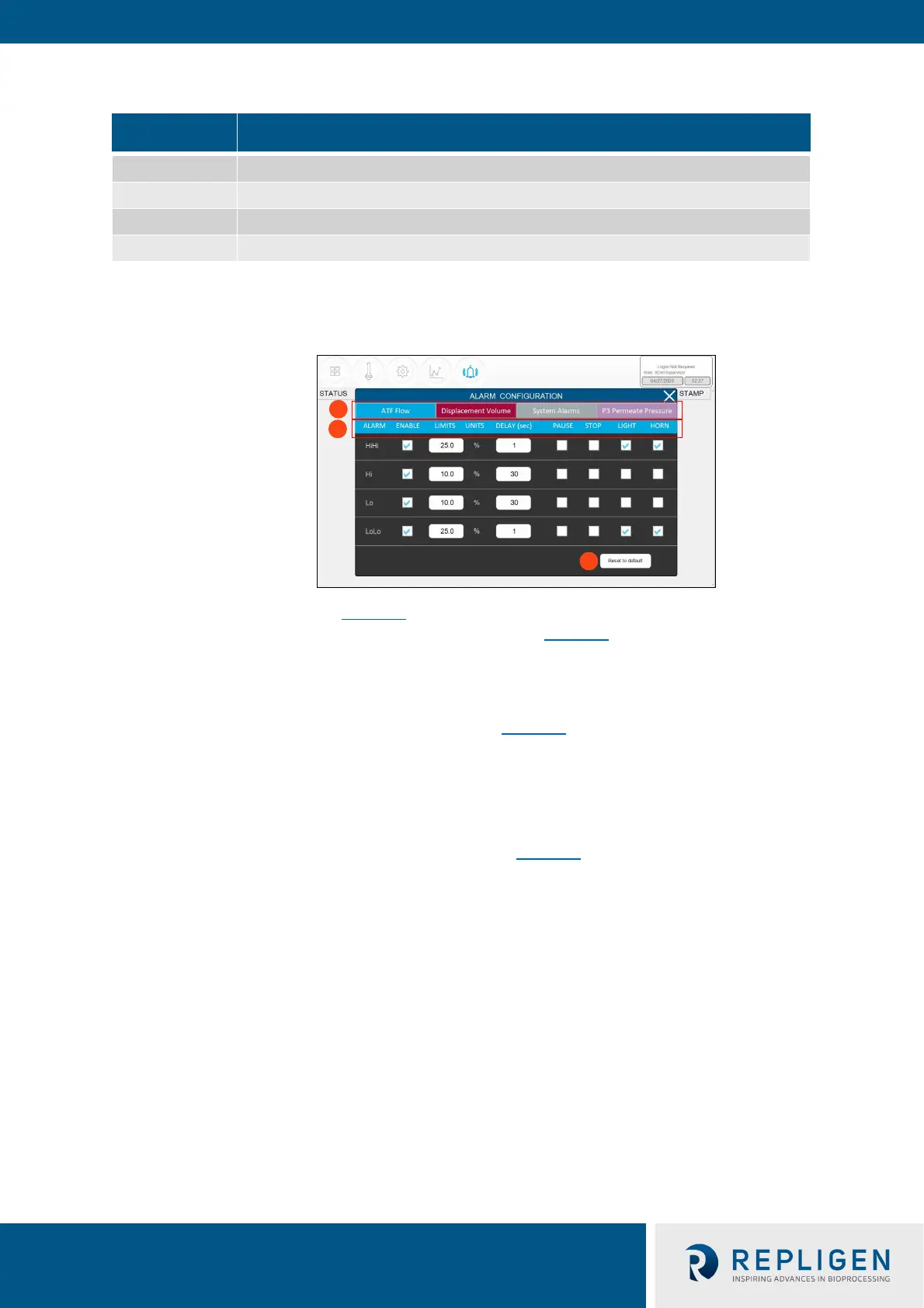
7.11.1 Alarm Configuration
Figure 33. Alarm Configuration example
1. Tabs
2. Commands
3. Reset to default values
The alarm configuration pop-up (Figure 33
) has four tabs. The commands row matches the color of
the active tab, indicating the active Alarm tab. As an example, Figure 33 displays ATF Flow tab as
active.
7.11.2 ATF Flow alarm configuration
Four different alarm options are available for ATF Flow (Figure 33
): HiHi, Hi, Lo, LoLo. You can select
the alarm type, parameter limit, and delay time. Simply uncheck the relevant box to turn off an
alarm. Flow alarms apply to all the ATF sizes and formats the controller can operate and are not
limited to the specific XCell ATF® Devices configured at the time the alarm is set.
Flow alarms are compared to the flow set point. Alarms are triggered when the flow set point is
exceeded or reduced by the specified limits. For example (Figure 33
), if the ATF Flow has a Setpoint
of 0.7 LPM, then the Hi 10% and HiHi 25% alarms would be triggered when the ATF Flow PV is >=
0.77 LPM and >= 0.875 LPM, respectively.
The Hi and Lo triggers are set at 10% in this example. If the ATF Flow equals or surpasses the 10%
limit (0.63 LPM or below for Lo, 0.77 LPM or above for Hi) in either direction, the relevant alarm
would get triggered.
Occasionally, alarms may be caused by trivial events such as noise or a mistake (human or
otherwise), which do not justify triggering actions that may include stopping the operation. The
Delay timer feature manages this situation. A 30 second delay timer requires that the alarm be
present for full 30 seconds after the first detection, for the alarm to display on the Alarms screen
and to trigger action.
The last four columns show actions the controller can take if an Alarm is triggered. Each box and
check box have a preset default value, which you may return to at any time by clicking the Reset to
Default button.