repligen.com XC-LAB-UG-V4
Table 6. A2B Tubing ID/OD
Device Tubing ID /OD Repligen Supplied Tube set?
XCell ATF® 1 1/8” / 1/4" Yes, part of device
XCell ATF® 2 1/4” / 3/8” Yes, supplied separately
XCell ATF® 4 3/8” / 5/8” Yes, supplied separately
Please reach out to your local Repligen representative for more information.
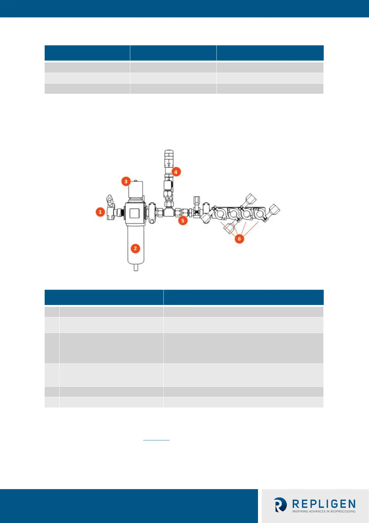
6.6 Supply Air Protection Assembly (SAPA)
Figure 7. SAPA components example
Table 7. SAPA components
Item Description
1 Manifold inlet Pressurized air from air supply
2 Filter unit
Filters air routing from air supply to manifold
Filter porosity: 0.3
3 Pressure regulator
Factory set air pressure supply regulator designed to
downregulate the supply air to a lower pressure required to
operate XCell ATF® 1, XCell ATF® 2 and XCell ATF® 4 (do not
4 Pressure relief valve
Factory set air supply pressure relief valve set to relieve if
inlet pressure exceeds the specification noted above (do not
5 Positive pressure supply manifold Pressurized air to XCell™ Lab Controller(s)
6 Manifold outlets Distributes air pressure to up to four XCell™ Lab Controllers
The SAPA normalizes air pressure from the lab utility line down to the required 15.6 psi. The
minimum utility air pressure requirement is 30 psi. A pressure relief valve provides safety in case of
the unlikely failure of the regulator (Figure 7)
. The regulator and relief valve are pre-set at the
factory; no modification is required by the end user. Installation should be performed or supervised
by an authorized Repligen service engineer.
Note: The SAPA must be installed with the air filter oriented downwards and plumbed.