repligen.com XC-LAB-UG-V4
7.7 ATF Main screen
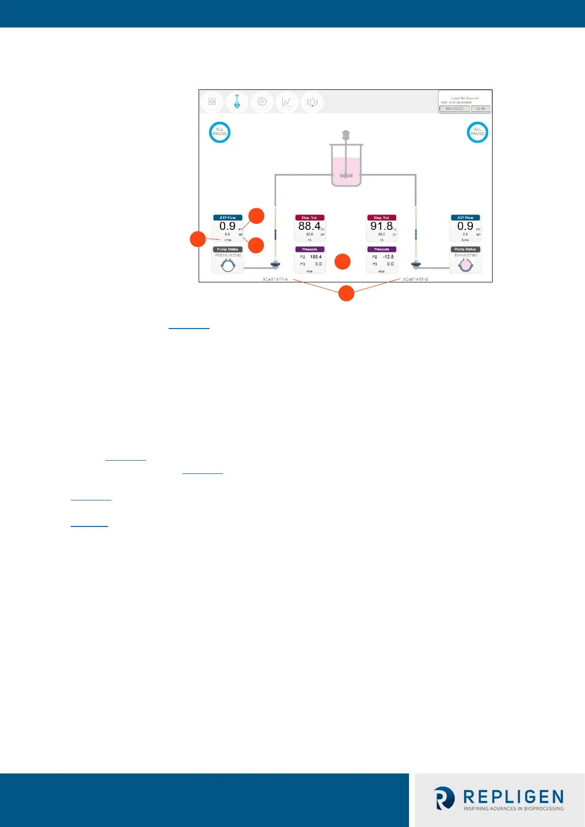
Figure 13. ATF main screen example two XCell ATF® Devices attached to same vessel
1. Units
2. Process value (bold)
3. Set point (SP)
4. XCell ATF® Device labels
5. P2, P3
The ATF main screen (Figure 13
) displays sensors and information appropriate for connec
ted
hardware. Figure 13 shows two XCell ATF® Devices on a single vessel. The permeate pressure (P3) is
also displayed on the screen (controller model XC-LAB-D-P).
N
ote: Throughout the software and this guide, each XCell ATF® Device is described as XCell™ ATF-A
and XCell™ ATF-B. XCell ATF® Device sizes are specified in Settings.
Note: The ATF DUAL box is only displayed when it is possible to run in dual mode (i.e. two same sized
XCell ATF® Devices on one bioreactor) and includes the synchronization mode of the pumps. In
independent mode, grey dotted lines appear from the ATF Flow box to the Pump Status box
(Figure 13
). In synchronized mode, grey dotted lines appear from the ATF DUAL b
ox to the
Pump Status box (Figure 14).
Figure 14 sh
ows two XCell ATF® Devices connected to one bioreactor as a dual system with the two
pumps working out-of-phase. The ATF DUAL box displays Out of Phase pump status. Please refer to
Table 10 f
or pump status details.
Note: To change the ATF Flow Set point, you must open the ATF DUAL box – you cannot change the
setpoints in the respective ATF-A Flow and ATF-B Flow boxes since the devices are now linked
out of phase.