repligen.com XC-LAB-UG-V4
7.8.7 Settings sub-menu
Figure 22. Settings sub-menu example
1. Settings
2. XCell ATF® Device Configuration
3. Bioreactor Configuration
4. Default Configuration
5. General Configuration
6. Service/Performance
The settings sub-menu (Figure 22
) d
isplays the options available to customize the device, bioreactor,
controller, and software settings.
7
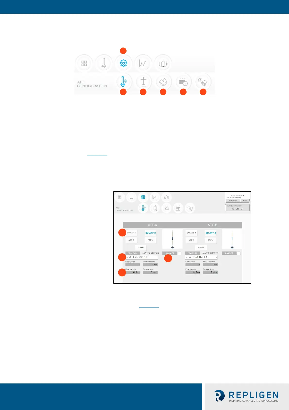
.8.8 XCell ATF® Device configuration
Figure 23. XCell ATF® Device configuration example
1. XCell ATF® Device size, format
2. Filter P/N (dropdown)
3. Default filter settings
4. Enable/disable P3 sensor
The XCell ATF® Device configuration sub-menu (Figure 23
) allo
ws selection of the XCell ATF®
Device(s) with a single click. Selection of a device opens default values and displays an image of the
chosen device. To run only one device with the D or D-P controller models, select NONE for the
other; device and the graphic will be removed from the device image appears blank. The ATF Main
screen will be updated as well.
O
nce an XCell ATF® Device selection is made, a filter part number can be selected from the drop-
down list. This enables the system to display the correct physical characteristics of the chosen filter
(shown below in grey), which is crucial for scale-up calculations.
Note: Uncheck the P3 box when not in use to avoid alarms due to lack of communication with the P3
sensor.