Balance connector wiring
When using FMA Wiring mode (Factory Default Setting)
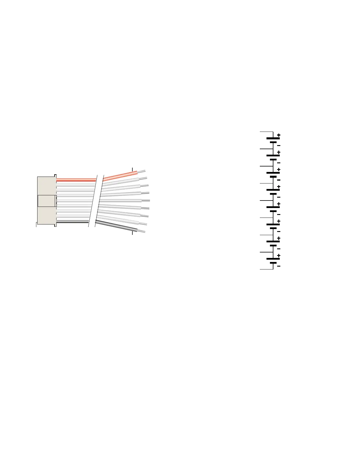
The following diagrams shows how a 9 pin Cellpro (JST PA series) balance connector
(REVO PN CPBP9P-10-US) must be wired to an 8s, 7s, 6s, 5s, 4s, 3s, 2s, and 1s
battery pack when the Dual PowerLab 8x2 is set to FMA Wiring mode (Factory default).
Whether the following is accomplished via the available adapters, or by physically
connecting (soldering) the 9 pin Cellpro pigtail to a battery pack directly, this is what the
PowerLab must see at its balance connector (output):
Pin 1
Red
Black
Node 5
Node 6
Node 7
Pack positive
Node 4
Node 3
Node 2
Node 1
Pack negative
8s Pack
Pack positive
(red), 29.6V*
Node 4, 14.8V*
Node 5, 18.5V*
Node 6, 22.2V*
Node 7, 25.9V*
Node 3, 11.1V*
Node 2, 7.4V*
Node 1, 3.7V*
Pack negative
(blk), 0V
Cell 5
Cell 6
Cell 7
Cell 8
Cell 4
Cell 3
Cell 2
Cell 1
* Nominal voltage with
respect to pack negative
FMA Cellpro Connector/FMA Wiring Mode
 Loading...