2.3 Product specifications
The FertiMiX-Go! is available in various configurations, because different dosing
channels, pumps, sensors and I/O modules can be added to the FertiMiX-Go!. This is
described in this and the following sections.
2.3.1 Basic configuration
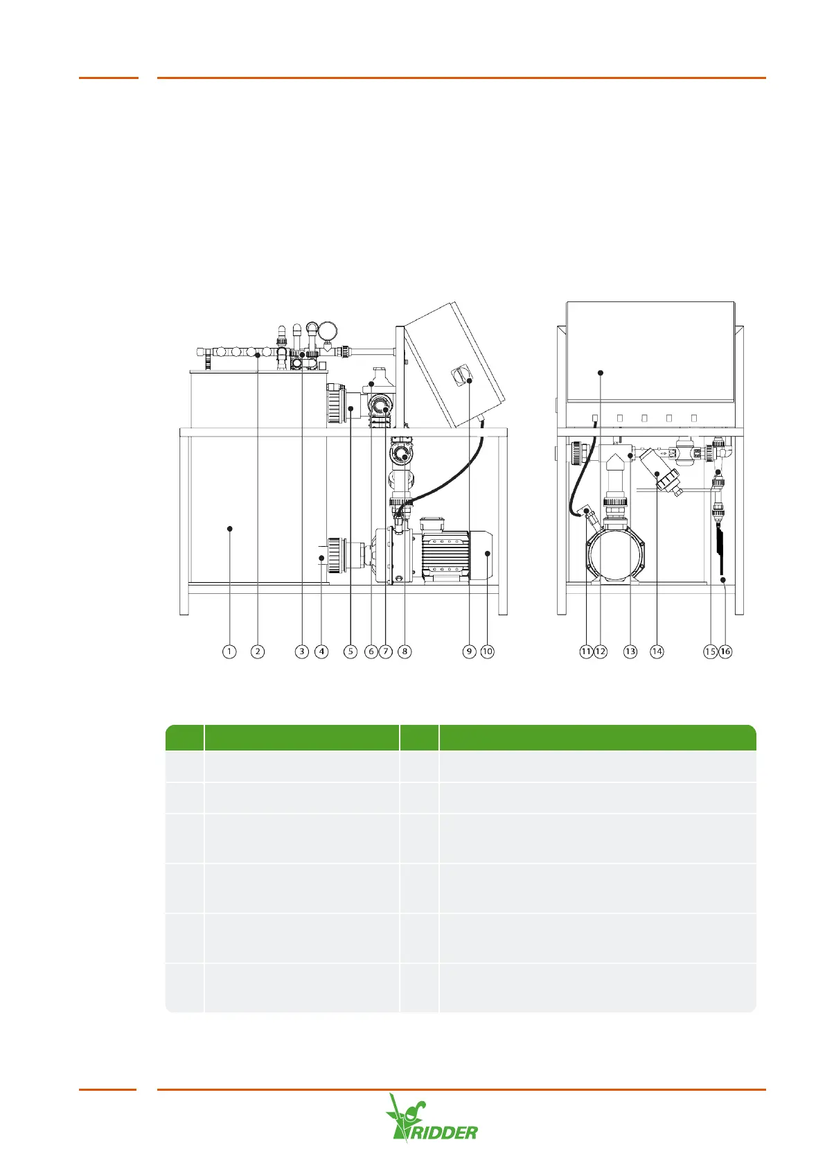
Figure 2-2 is a diagram of the components of the FertiMiX-Go!.
Figure 2-2: Side and front view of the FertiMiX-Go!
No. Description No. Description
1 Mixing tank 9 Power switch / emergency stop
2 Dosing module 10 System pump
3 Measurement module
(location of sensors)
11 Thermal cut-out for pump (optional)
4 Water outlet of mixing
tank
12 Integrated process computer and control
panel
5 Water inlet of mixing tank
water
13 Pressure module with filter
6 Filling module with float
valve
14 Screen filter (500 microns)
FertiMiX
11