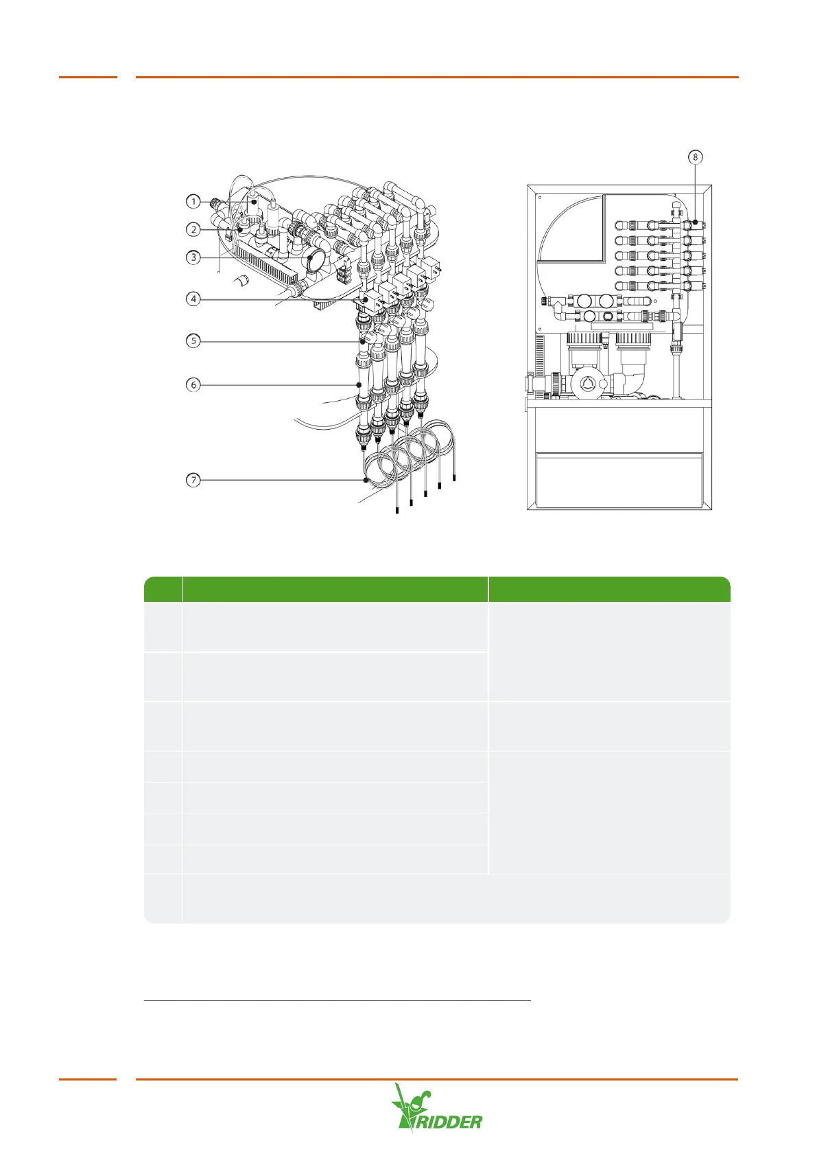
The figure below shows the most complete configuration.
Figure 2-6 Dosing module and measurement module
No. Description Part of
1 pH control sensor and pH verification
sensor
Measurement module
2 EC control sensor and EC verification
sensor
3 Pressure gauge after filter, 0.0 - 2.5 bars -
> 2.2 bars
4 Dosing valve Fertilizer dosing channel
5 Needle valve
6 Sight glass of venturi flow meter
7 Suction hose with filter
1
8 Optional acid dosing channel, recognizable by location and different colour
sight glass
1
If necessary, shorten the included suction hoses or replace them by hoses of a
different length and/or diameter
FertiMiX
16