AgilityInstallerManual
Page 2-1
Chapter 2 Installing the Agility
ThischaptercoverstheinstallationproceduresoftheAgility,asfollows:
AgilityMainComponents,page2‐1
MountingtheAgility,page2‐2
Choosingth e mountinglocation,page2‐2
WallMountingtheAg ilitypage2‐2
ConnectingtheBackupBattery,page2‐5
ConnectingtheAgilitytoPowerSupply,page2‐6
GroundConnection,page2‐6
DIPswitchsetting,page2‐8
Connectingatelephone linetotheAgility,pag e 2‐9
SIMCardInstallation,page2‐9
ExternalAudioUnit,page2‐12
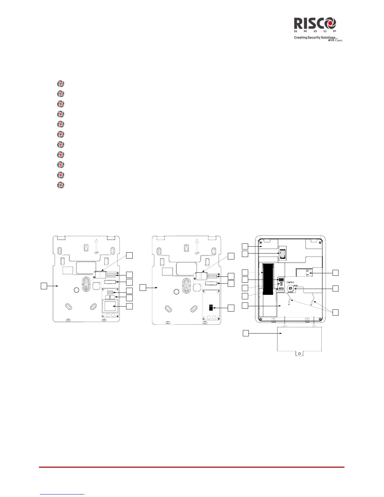
Agility Main Components
Theillustrationbelowshowstheinternal components(whentheMountingBracketis
disassembledfromtheBackPanel).
1
2
4
3
5
6
7
ConfigurationA
1
2
4
3
5
ConfigurationB
8
10
LOCK
OPEN
1234
ON
11
12
13
14
9
15
18
17
16
Figure1:AgilityMainComponents
1. InstallationBracket 7. Transformer 13 RS232communicationconnector
2. TelephoneJacks 8. BackPanel 14. Batterycompartment
3. AudioUnitterminals 9. SIMCardsocket 15. Batterycompartmentcover
4. Ribbonflatcablejack 10. Ribbonflatcable 16. Batteryflingleads
5. ACconnection
terminals/DCSocket 11. DIPSwitches 17. Tamperswitch
6. Fuse 12 PTMconnector 18. IPCardnetworkconnector
 Loading...