AgilityInstallerManual
Page 2-3
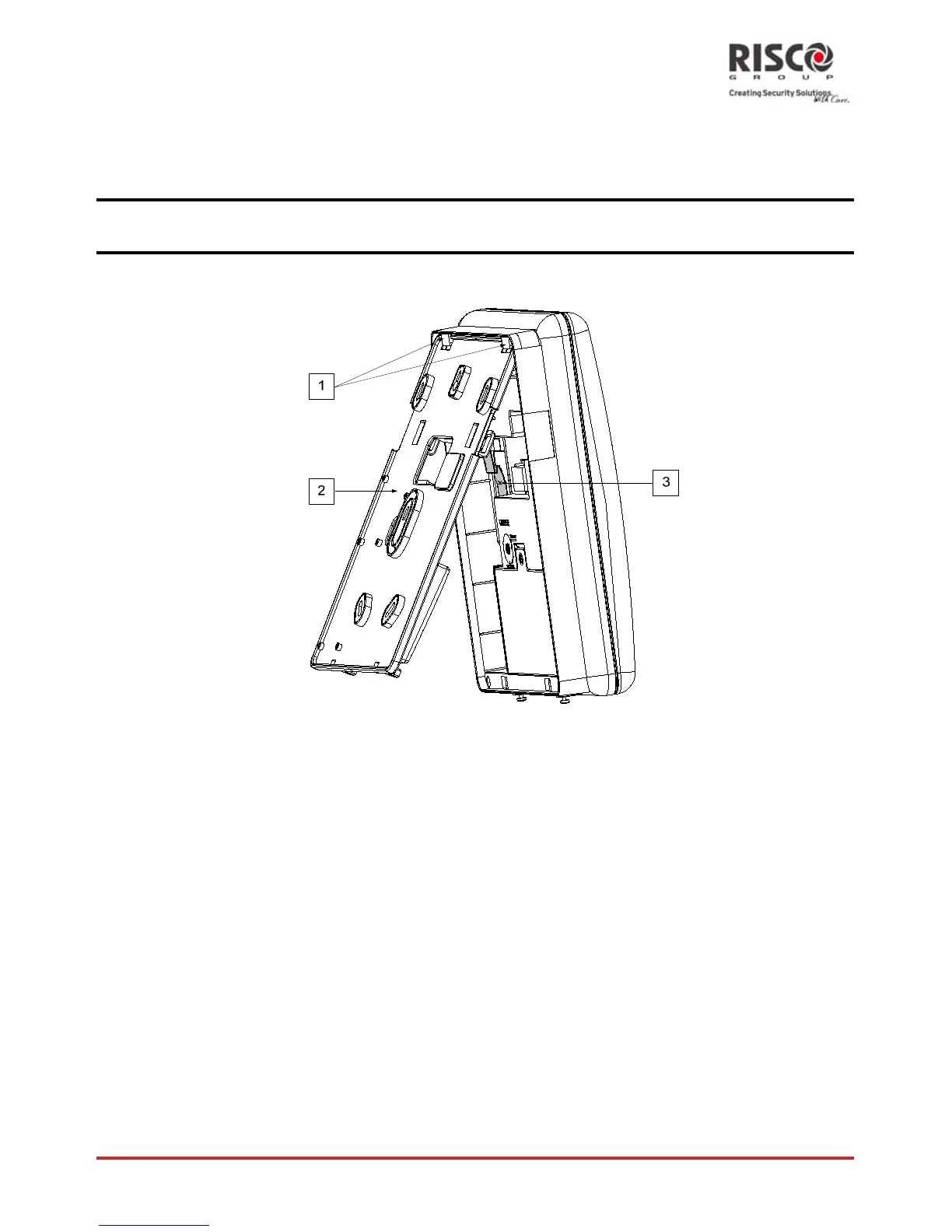
b. Gently,pulluptheMountingbrackettoa45°angleandslideitdowntorelease
theMountingbracket(2,Figure3)fromthetwolockingtabs(1,Figure3)atthe
topoftheunit.
Note:DonotopentheMountingbrackettoalargerangleinordernottobreakthetwotoptabsandnotto
tearuptheribbonflatcableconnectingthepowersupplyunittothefrontpanel(PCB).
c. Disconnecttheribbonflatcable(3)fromthepowersupplyunitwhileleavingit
connectedtotheMainpanel.
Figure3:MountingBracketremoval
2. HoldtheMountingbracketagainstthewallasatemplateandmarkthelocationsfor
themountingholes(5mountingholesitem1,andanadditionalholeforsecuringthe
tamperprotectionbracketitem2,areavailable,seeFigure4).
3. Drillthedesiredmountingholesandplacethescrew
anchors.Usethesupplied5
PhilipspanheadscrewstoattachtheMountingbrackettothewall(ST4.2mmx32
mmDIN7981).
4. Accordingtothelocationofthewallcables,routeandinsertthewiresandcablesvia
thecable’sopenings(3)(includingACcableandtelephonecable),seefigure3.
5. Ifrequired,removecableknockouts(5)toallowwirepassage.
6. Anchorcableswithdedicatedhooks(4).
 Loading...