Robertson AP21 and AP22 Autopilots
64 20220596E
4.11 Control unit installation
Avoid mounting the control unit(s) where it is easily exposed to
sunlight, as this will shorten the lifetime of the display. If this is
not possible, make sure the units are always covered with the
white protection cover when not used.
Panel mounting of AP22
• Drill the 4 mounting holes and make
a panel cut-out according to supplied
template.
• Place one of the three supplied
gaskets between the panel and the
unit with the interlocking feature
correctly orientated (see figure).
• Use the supplied screws to fasten the
control unit to the panel. Do not over-
tighten the mounting screws!
• Apply the front panel corners.
• Connect the Robnet cable(s) to the
control unit connector(s) (See note on
page 66).
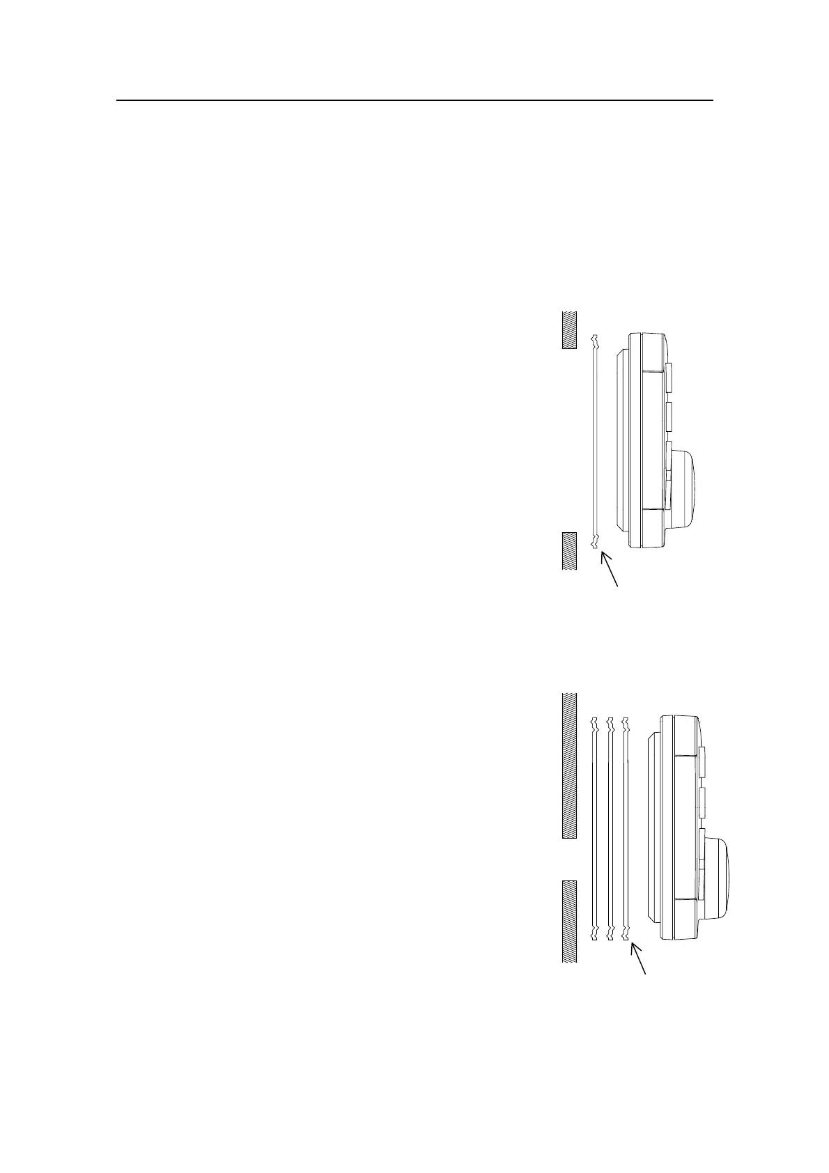
Alternative panel mounting of AP22
Note ! This way of mounting is simpler, but will lift
the unit from the panel surface. When
installed adjacent to IS11 instruments there
will be a difference in height between the
autopilot and the instruments.
• Use the template and drill hole(s)
only for the connectors.
• Place all three gaskets between panel
and unit with the interlocking feature
correctly orientated (see figure).
• Follow above panel mounting
instructions.
Do not over-tighten the mounting screws!
This side towards
control unit
This side towards
control unit