Robertson AP21 and AP22 Autopilots
70 20220596E
Use the supplied mounting kit and drill the holes through the
centre of the slots in the sensor or the mounting brackets.
Note ! The compass face plate on the RFC35 is the TOP. Never mount it
upside down! Level the sensor as close to horizontal as possible.
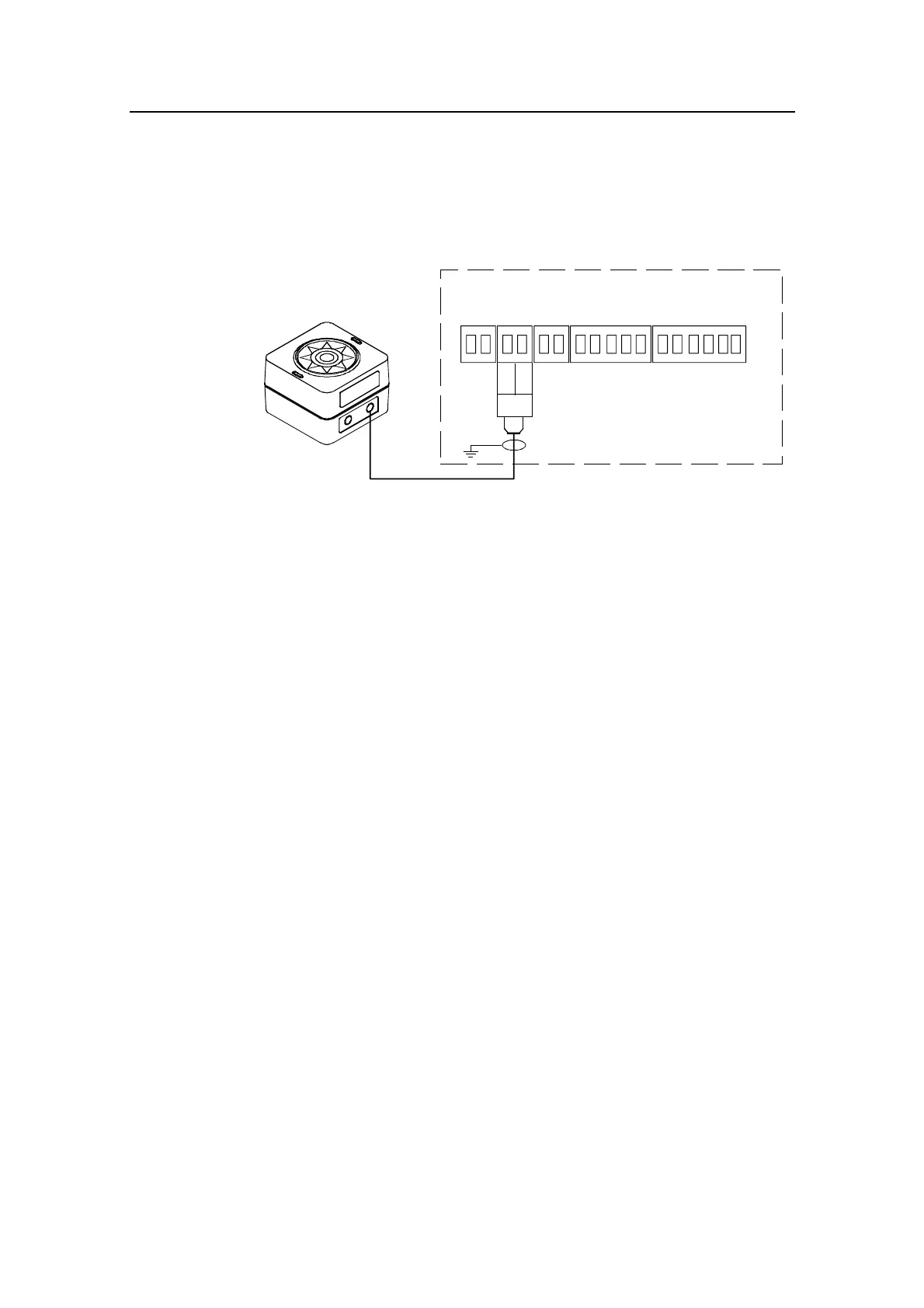
RFC35
FLUXGATE
COMPASS
JUNCTION UNIT
MAIN PCB
Heading
Sensor
*
* NON POLARIZED
(COLOR INDEPENDENT)
HS+
HS-
Figure 4-13 RFC35 connection
4.15 RFC35R Rate Compass installation
The RFC35R Rate Compass also contains a magnetic fluxgate
sensor, which means you have to take the same precautions at
installation as for the standard RFC35 (see previous page). On
steel hull boats, however, it should be installed 0,75-1 meter (2,5-
3 feet) above the steel deck to obtain optimum performance.
• Connect the Robnet connector to the AP22 Control Unit or
CI300X or NI300X if installed, see Figure 4-9 on page 66.
Alternatively, if there is no free receptacle, cut the connector
from the cable and connect the wires in parallel with the
wires shown on Figure 4-10 using the same colour code. Do
not connect the yellow and the green wire, but secure them from
connection to the terminal or chassis.
• Select RFC = ROBNET in the Interface Menu.
• Select RFC as compass in the User Setup Menu to activate the
RFC35R as steering compass.
• Perform the compass calibration as described on page 101.
Note ! After turn on the compass will stabilize in less than 30 seconds, but it
will need another 10 minutes to get the full effect of the rate sensor.
Refer to page 102 to compensate for any permanent off-set after
the calibration is completed.