Robertson AP21 and AP22 Autopilots
76 20220596E
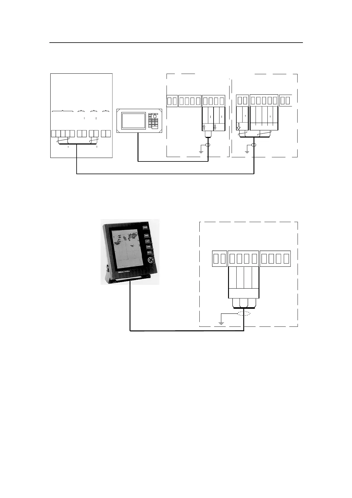
4.23 Databox/J300X
RX1
RX1+
J300X JUNCTION UNIT
MAIN PCB
DATABOX (NMEA Input)
Vbat+
Spare
Gnd
Red Wh
Bn
Gn Blk
TX1
TX1+
NMEA
Output
BRN
BLK
INPUT +
INPUT
WHITE
BLACK
INPUT +
INPUT
GRN
WHT
RED
SOUNDER
INPUT
COMPASS
INPUT
RADIO NAV
INPUT
NMEA BUS
TO
REPEATERS
IS11 DATABOX
*
J300X JUNCTION UNIT
POWER PCB
TB8
TB9
TB10
RX2
RX2+
NAV. RECEIVER
OR PLOTTER
NMEA
Input2
TX2
TX2+
NMEA
Output2
TWISTED PAIR
CABLE
*
RX1+
RX1
TX1
TX1+
Figure 4-22 IS11 Databox / J300X connection
4.24 Radar Clock/Data
J300X JUNCTION UNIT
POWER PCB
Radar
TB8
TB9
TB10
Data_h
Data_c
Clk_h
Clk_c
ANRITSU
OR
FURUNO
RADAR
Figure 4-23 Radar Clock/Data connection
4.25 IS11 Instrument installation
The IS11 Instruments (RUDDER, COMPASS) are designed for
panel mount in exposed locations. See separate installation
description enclosed with the units.
Note ! You can only connect the instrument as shown if the supply voltage is
12 V. If the supply has a 24 V or 32 V source a separate 12 V source
must be provided for the instrument (Red/black).