Robertson AP21 and AP22 Autopilots
72 20220596E
TB6
J3000X/J300X JUNCTION UNIT
POWER PCB
TB3
TB4
TB5
TB7
S35
STEERING LEVER
TB1 TB2
Lamp
Stbd
Port
Gnd
Brn/Wh
Pnk/Gry
Yel
Grn
NOTE!
Disregard the colour code
on the terminal label.
REMOTE
Figure 4-15 S35 connection
The unit is opened by removing the three screws on the back
cover. Inside are two sets of micro-switches, a printed circuit
board with a plug-in terminal, a jumper strap and other
components according to the circuit diagram that accompanies
the lever at delivery.
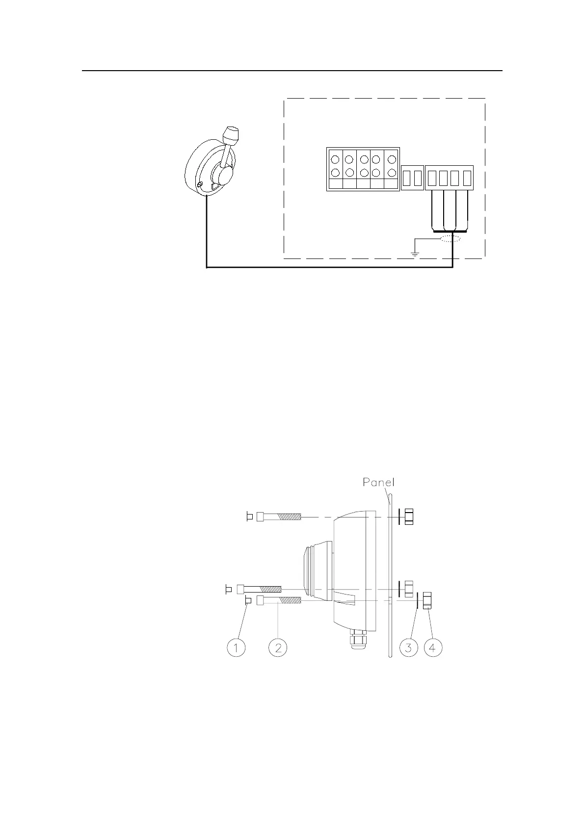
4.18 FU35 Follow Up Lever installation
The unit is mounted to bulkhead or panel by three Allen screws
(2) from the front. See Figure 4-16. The head of the screws may
be covered with the three enclosed caps (1) .
Figure 4-16 FU35 mounting
The handle can be screwed into the knob pointing upwards or
downwards. The knob can also be rotated directly by hand
without the handle.