Installation
20220596E 73
Strip about 25 mm (1”) of the cable insulation and pull the
shield backwards. Secure the cable the same way as the other
cables in the junction unit and connect the wires in parallel with
the cable shown on Figure 4-17 using the same colour code.
On-Off
Vsys+
JUNCTION UNIT
MAIN PCB
Bus+
Vsys
Alarm
Bus
CONTROL
UNIT
FU35
STEERING
LEVER
Yellow
Pink
White
Grey
Green
Brown
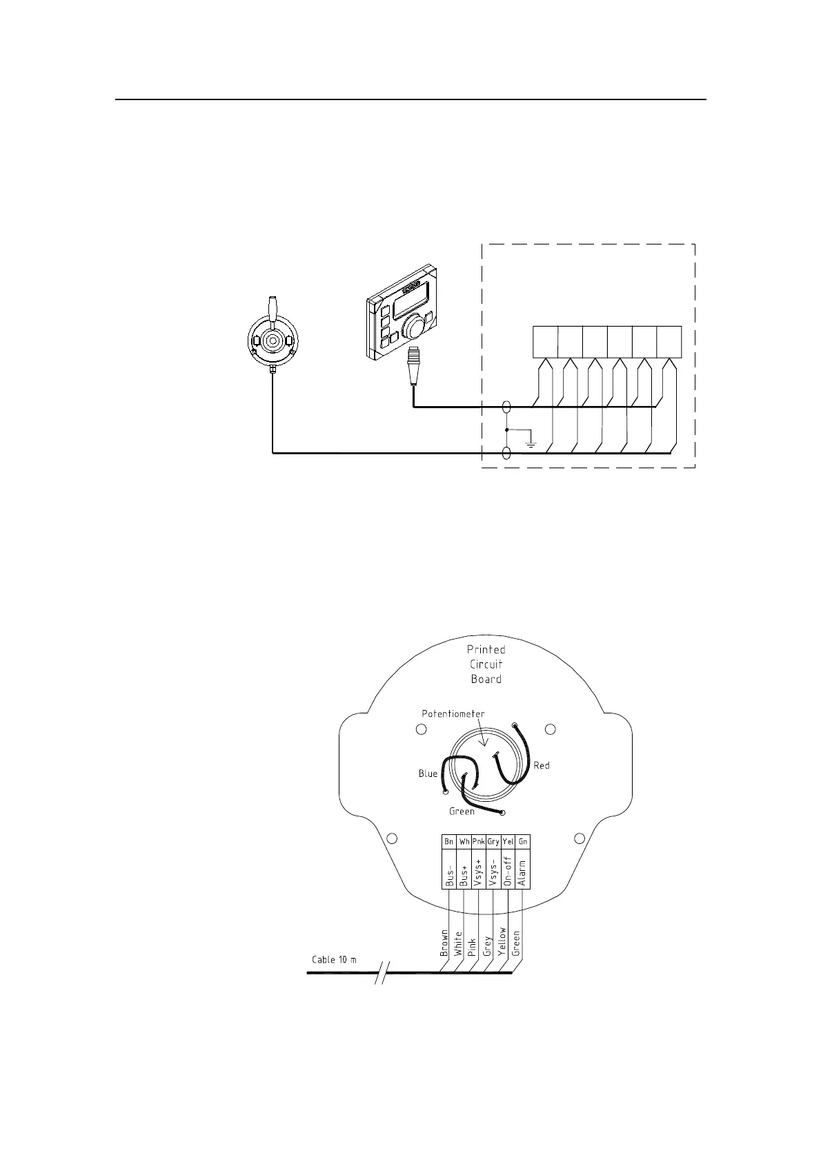
Figure 4-17 FU35 connection
The cable gland can also be mounted in the back cover.
The unit is opened by removing the four screws on the back
cover. Inside are a potentiometer and a printed circuit board
with plug-in terminals. Internal wire connection is shown on
Figure 4-18.
Figure 4-18 FU35 Internal connections