Rockwell Automation Publication 1715-UM001J-EN-P - December 2020 71
Chapter 2 Installation Instructions
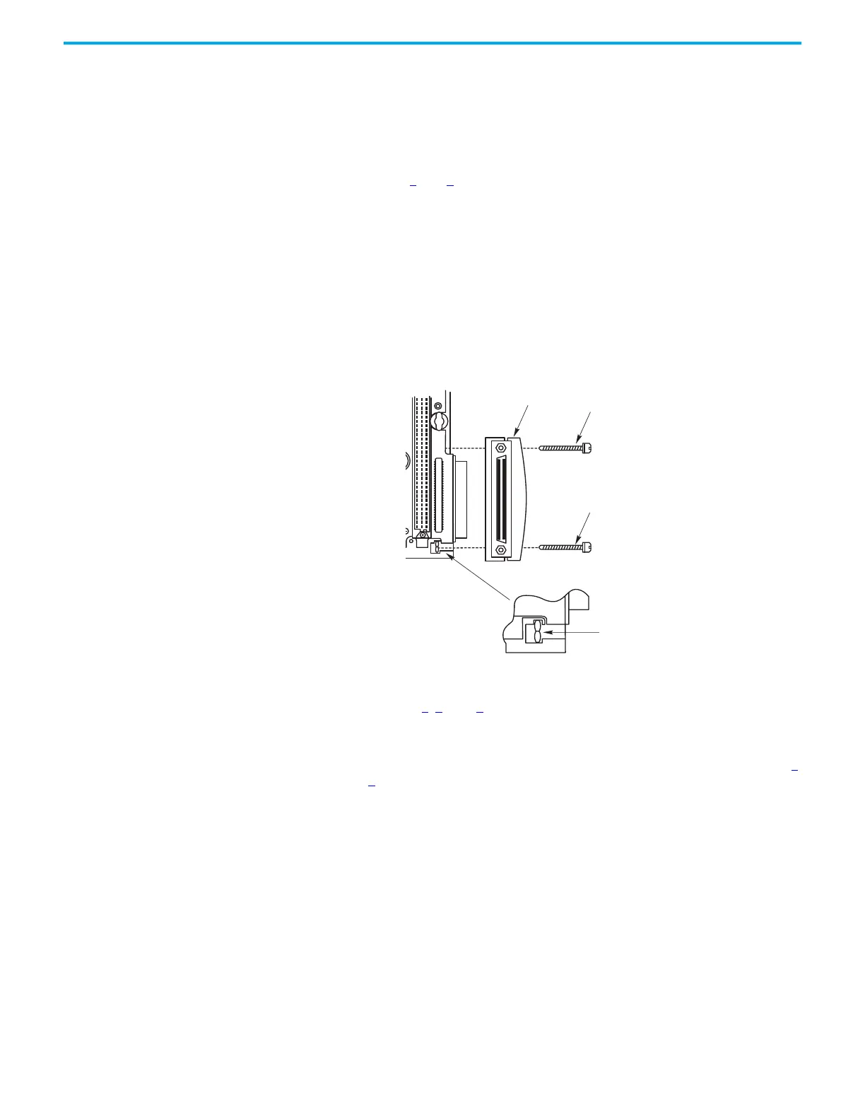
4. Secure the plug or socket assembly by inserting the two M3 socket cap
screws.
5. Tighten the screws with a 2.5 mm Allen wrench.
6. Install the cable end into the plug or socket assembly and tighten the
retaining screws by hand.
7. Fit the cable plug or socket assembly to the other I/O base unit and secure
as in steps 3
and 4.
8. Fit the other end of the cable into the cable plug or socket assembly.
Connect to a 1715-A2A 2-slot Adapter Base Unit
1. When installing the expansion cable from the right-hand side, insert a
cable plug assembly into the 1715-A2A adapter base unit connector.
2. Follow steps 3
, 4, and 5.
3. Insert the cable end into the cable plug assembly and tighten the
retaining screws by hand.
4. Fit the cable socket assembly to the I/O base unit and secure as in steps 4
and 5
.
5. Fit the other end of the cable into the cable socket assembly.
Extending from
right hand side
3
2
3
4
1
2
3
4
1
2
32082 M
Cable Plug Assembly
M3 Socket Cap Screw
M3 Socket Cap Screw
M3 Nut

 Loading...


