Rockwell Automation Publication 2198-RM004C-EN-P - March 2022 27
Chapter 2 Replacement Considerations
The analog output (AO) on terminal IOD-23 has a 10-bit resolution. The analog
output is a single-ended signal and referenced to analog common (ACOM) that
can be assigned to the following:
•Not Assigned
• RMS Phase Current
• RMS Peak Current
• Motor Velocity
• Phase Current U
• Phase Current V
• Phase Current W
•I
q
Current
•I
d
Current
Kinetix 5100 Analog Outputs
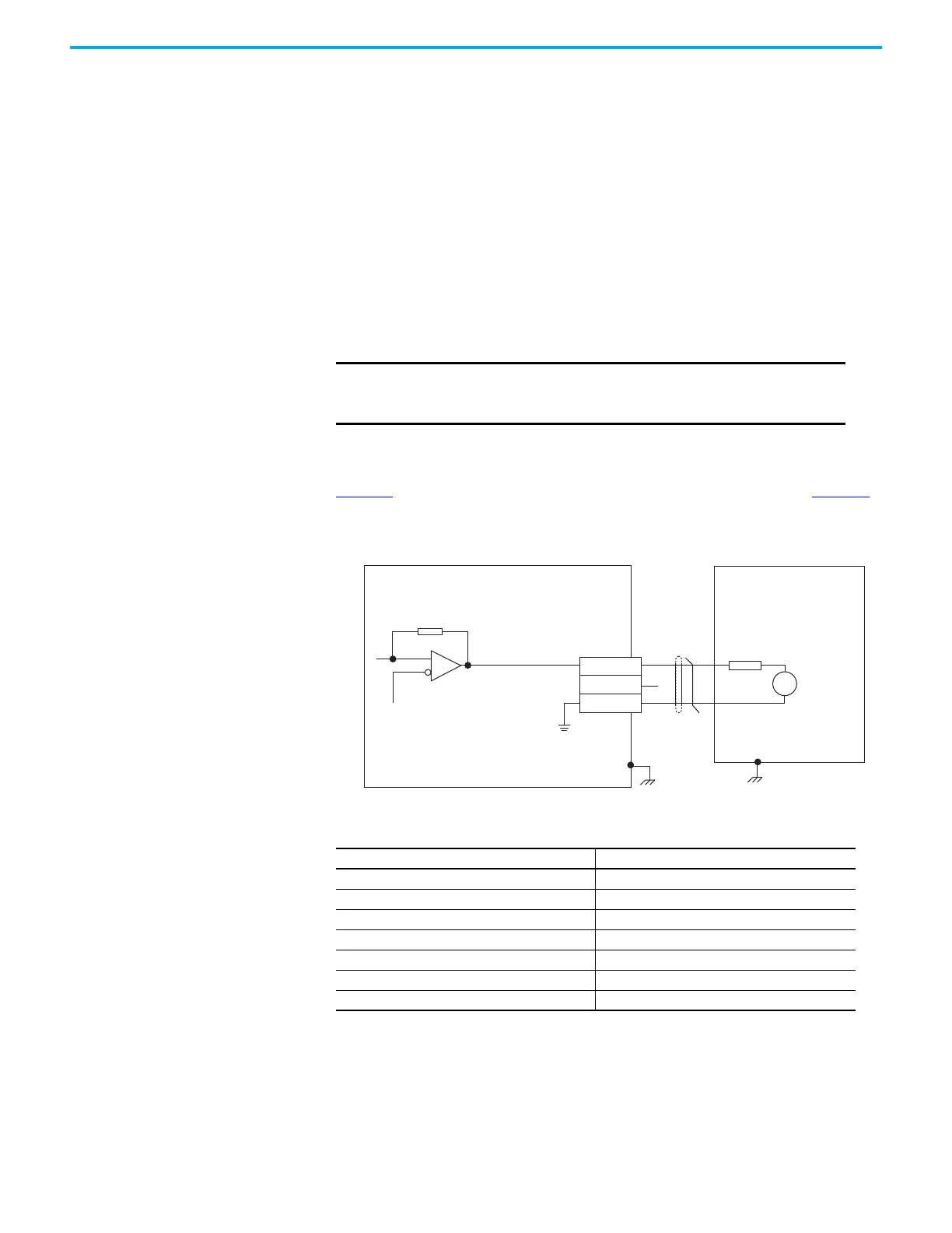
Figure 6 shows the analog output circuit for the Kinetix 5100 Drives. Table 28
lists the Kinetix 5100 analog output specifications.
Figure 6 - Kinetix 5100 Analog Output Circuit
The Kinetix 5100 servo drive provides two single-ended analog outputs (MON1
and MON2) referenced to an analog ground.
IMPORTANT Output values can vary during power-up until the specified power
supply voltage is reached. MotionView software refers to phase
current U, V, and W as R, S, and T respectively.
Table 28 - Kinetix 5100 Drives Analog Output Specifications
Parameter Kinetix 5100
Analog Output Resolution 10 bits min
Analog Output Current max 1 mA
Analog Output Voltage –8V … +8V DC, or –10…+10V DC, configurable
Analog Outputs Scan Time 0.25 ms max
Offset Error 100 mV max
Gain Error 5% max
Bandwidth 50 Hz min
AGND
24 kΩ
Output:
1 mA, max
8 kΩ
-10V/+10V
Full-scale
V
13
16
15
MON1
MON2
Analog GND
Servo Drive
Controller
I/O Connector with
2198-TBIO Expansion Block
 Loading...


