108 Rockwell Automation Publication 750-RM004A-EN-P - April 2018
Chapter 2 Drive Configuration
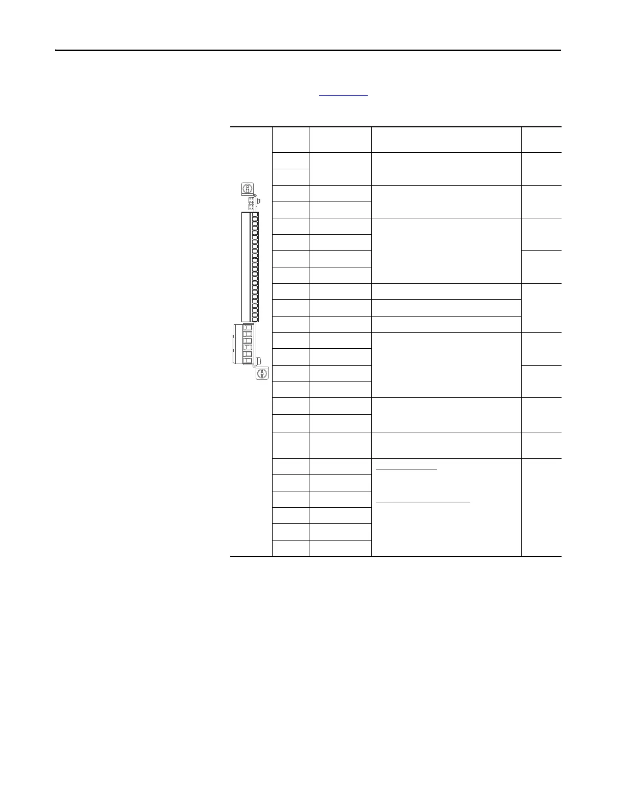
The 20-750-2263C-1R2T I/O module terminals and related parameter table
are from publication 750-IN100
, and are shown here for reference only.
Table 64 - TB1 Terminal Designations
Terminal Name Description Related
Param
(4)
(4) I/O Module parameters will also have a Port designation.
Sh Shield Terminating point for wire shields when an EMC
plate or conduit box is not installed.
Sh
Ptc– Motor PTC (–) Motor protection device (Positive Temperature
Coefficient).
40
on Port nn
Ptc+ Motor PTC (+)
Ao0– Analog Out 0 (–) Bipolar, ±10V, 11-bit & sign, 2 kΩ minimum load.
4-20 mA, 11-bit & sign, 400 Ω maximum load.
75
on Port nn
Ao0+ Analog Out 0 (+)
Ao1– Analog Out 1 (–) 85
on Port nn
Ao1+ Analog Out 1 (+)
–10V –10V Reference 2 kΩ minimum.
10VC 10V Common For (–) and (+) 10V references.
+10V +10V Reference 2 kΩ minimum.
Ai0– Analog Input 0 (–) Isolated
(2)
, bipolar, differential, 11-bit & sign.
Voltage Mode: ±10V @ 88 kΩ input impedance.
Current Mode: 0-20 mA @ 93 Ω input impedance.
(2) Differential Isolation - External source must be maintained at less than 160V regarding PE. Input provides high common mode
immunity.
50, 70
on Port nn
Ai0+ Analog Input 0 (+)
Ai1– Analog Input 1 (–) 60, 70
on Port nn
Ai1+ Analog Input 1 (+)
24VC 24V Common Drive supplied logic input power.
200 mA max. per I/O module
600 mA max per drive
+24V +24V DC
Di C Digital Input
Common
Common for Digital Inputs 0…5
Di 0 Digital Input 0
(1)
(1) Digital Inputs are either 24V DC (2262C) or 120V AC (2262D) based on module catalog number. Ensure applied voltage is correct
for I/O module.
24V DC (30V DC Max.) - Opto isolated
High State: 20…24V DC 11.2 mA DC
Low State: 0…5V DC
120V AC (132V AC Max.) 50/60 Hz
(3)
- Opto
isolated
High State: 100…132V AC
Low State: 0…30V AC
(3) For CE compliance, use shielded cable. Cable length should not exceed 30 m (98 ft).
1
on Port nn
Di 1 Digital Input 1
(1)
Di 2 Digital Input 2
(1)
Di 3 Digital Input 3
(1)
Di 4 Digital Input 4
(1)
Di 5 Digital Input 5
(1)
Sh
Sh
PTC–
PTC+
Ao0–
Ao0+
Ao1–
Ao1+
–10V
10VC
+10V
Ai0–
Ai0+
Ai1–
Ai1+
24VC
+24V
DiC
Di0
Di1
Di2
Di3
Di4
Di5
 Loading...


