Rockwell Automation Publication 750-RM004A-EN-P - April 2018 133
Enclosure Information Appendix A
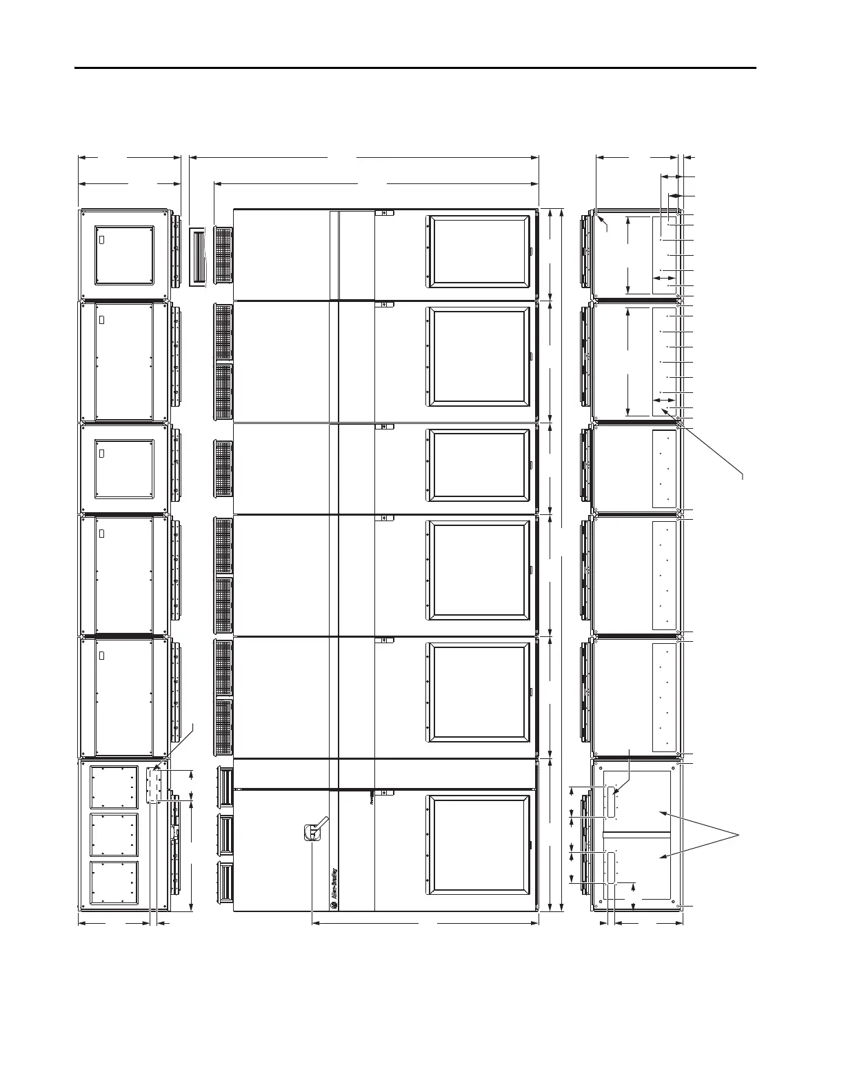
Figure 43 - Frame 12 PowerFlex 755TR
4606
(181.3)
1000
(39.4)
800
(31.5)
0 (0)
935 (36.8)
450
45
(1.8)
200
(7.9)
200
(7.9)
230
(9.1)
186
(7.3)
1481
45
(1.8)
709
(27.9)
153
(6.0)
600
(23.6)
800
(31.5)
1800 (70.9)
1735 (68.3)
1000 (39.4)
800
(31.5)
600
(23.6)
509
(20.0)
153
(6.0)
IP21, UL Type 1
2132
(83.9)
2291
(90.2)
IP21, UL Type 1
676
(26.6)
721
(28.4)
3468 (136.5)
3568 (140.5)
3668 (144.4)
3768 (148.3)
3868 (152.3)
3268 (128.7)
3368 (132.6)
3135 (123.4)
2600 (102.4)
2535 (99.8)
3935 (154.9)
3200 (126.0)
4535 (178.5)
4000 (157.5)
4268 (168.0)
4368 (172.0)
4468 (175.9)
4068 (160.2)
4168 (164.1)
36
(1.4)
150
(5.9)
105
(4.1)
535
(21.1)
Power BayInput Bay Power Bay Power Bay
Control Cables - Top Entry
Signal Cables - Top Entry
Power Bay Power Bay
Input Power Cables - Bottom Exit
(Plate is marked with recommended gland or conduit hole pattern.)
Input Power Cables - Bottom Entry
Mounting Holes
 Loading...


