Home
Rockwell Automation
Controller
Allen-Bradley PowerFlex 700S
Migration Guide
Page 132
Rockwell Automation Allen-Bradley PowerFlex 700S - Page 132
148 pages
Manual
To Next Page
To Next Page
To Previous Page
To Previous Page
Loading...
132
Rockwell Automation Publication 750-RM
004A-EN-P - April 2018
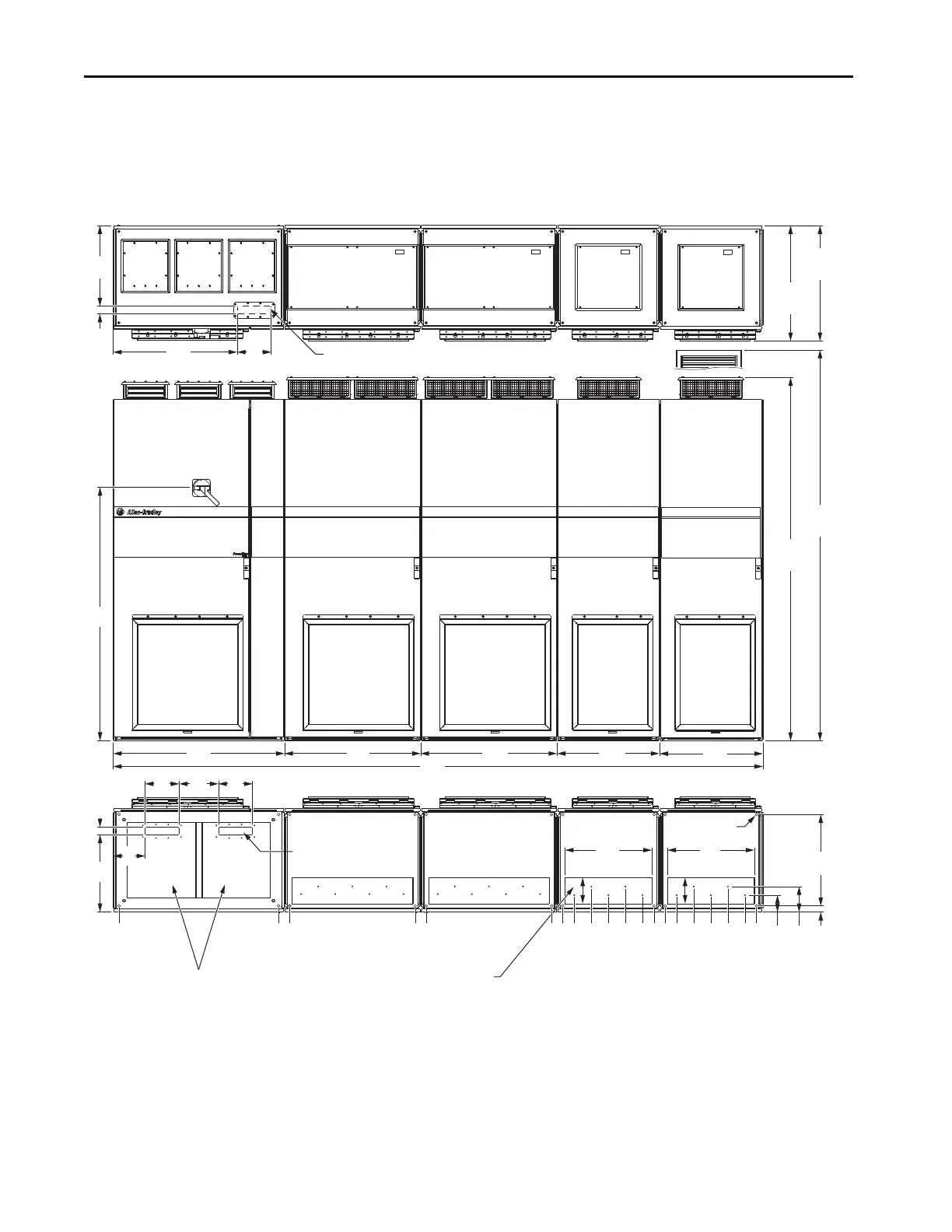
Appendix A
Enclosure Information
Figure 42 - F
rame 11 Po
werFlex 755TR
3206
(126.6)
1000
(39.4)
800
(31.5)
0 (0)
935 (36.8)
450
(17.7)
45
(1.8)
200
(7.9)
200
(7.9)
230
(9.1)
186
(7.3)
1481
(58.3)
200
(7.9)
726
(28.6)
473
(18.6)
45
(1.8)
3735 (147.0)
3200 (126.0)
3468 (136.5)
3568 (140.5)
3668 (144.4)
3268 (128.7)
3368 (132.6)
3135 (123.4)
2868 (112.9)
2968 (116.9)
3068 (120.8)
2668 (105.0)
2768 (109.0)
600
(23.6)
509
(20.0)
153
(6.0)
509
(20.0)
153
(6.0)
IP21, UL Type 1
2132
(83.9)
IP54, UL Type 12
2291
(90.2)
IP21, UL Type 1
676
(26.6)
IP54, UL Type 12
721
(28.4)
600
(23.6)
600
(23.6)
2600 (102.4)
2535 (99.8)
1800 (70.9)
1735 (68.3)
1000 (39.4)
36
(1.4)
150
(5.9)
105
(4.1)
535
(21.1)
Powe
r
B
ay
Input Bay
Po
wer Bay
Powe
r Bay
Signal
Cabl
es - T
op En
try
Motor Cables - Bott
om Exit
(Plate is marked with recommended
gland or conduit hole pattern.)
Powe
r
B
ay
Contr
ol Cables - Bottom Entry
Po
wer Cables - Bottom E
ntry
Mounting Holes
131
133
Table of Contents
Main Page
Default Chapter
3
Table of Contents
3
Overview
5
Preface
5
Abbreviations
6
General Precautions
7
Parameter References
7
Compatibility Quick Check
8
Before Migration
9
General Information
9
Additional Resources
10
Chapter 1 About the Powerflex 700S AC Drive
13
Selection Considerations
13
Powerflex 700S Catalog Number Explanation
15
About the Powerflex 755T
17
Powerflex 755T Product Catalog Number Explanation
18
DC Input Inverter Considerations
21
AC Input Drive Power Source Considerations
22
Power Source Sizing
23
Other Loads Powered from the AC Power Source
23
Power Source Grounding
24
Recommended Grounding Scheme
25
EMI Filters
26
Power Filter Jumpers
26
Circuit Protection
27
Power Cables
30
Other Power Circuit Considerations
31
Control Power
31
Inverter Output Filtering
34
Specification and Features Comparison
35
Cross Reference Guides
46
AC Input Electrical Cross-Reference
46
DC Input Electrical Cross Reference
51
AC Input Dimensional Cross Reference
56
DC Input Dimensional Cross Reference
61
Device Ports and Main Control Board I/O
66
Powerflex 700S Device Ports and Main Control Board
66
Control Board
71
Customer Power Terminal Comparison
74
Powerflex 700S Customer Power Terminal Locations and Specifications
75
Powerflex 755T Customer Power Terminal Locations and Specifications
81
Hardware Enable Circuits
74
Control Terminal Comparison
87
Powerflex 700S Standard I/O
87
Powerflex 755T I/O Option Modules
88
Chapter 2 Overview
89
Drive Configuration
89
Configuration Software and HIM Versions
91
Parameter Comparison
92
Parameter Scaling
92
Powerflex 700S Parameter Assignment
92
Powerflex 755T Parameter Assignment
92
Standalone Drive Configuration
100
Example, Three-Wire Control with Analog Speed Reference
100
And Encoder Feedback
100
Comparison
103
Powerflex 755TL/TR Drive Control
105
Safety Configurations
109
Powerflex 700S Safety Options
109
Powerflex 755T Safety Options
110
Migration Solutions
110
Powerflex 700S Drivelogix 5730 Configurations
111
Migration Solutions
111
Communication Configuration
113
Chapter 3 Scaling of Reference and Feedback
114
Powerflex 700S DPI Communications
115
Powerflex 755T Communications
115
Logic Command Word Comparison
117
Datalink Handling Comparison
119
16-Bit Processors
120
Appendix A Dimensions and Enclosure Types
121
AC Input Dimensions
122
DC Input Dimensions
134
Enclosure Information
121
Cooling and Airflow Comparison
139
Powerflex 700S Installation Requirements
140
Powerflex 755T Product Installation Requirements
141
Minimum Clearances
143
Powerflex 755T Product Equipment Handling Options
139
Module Service Cart
139
DC Precharge Module Service Lift
139
Power Module Service Ramp
139
Power and Filter Module Storage Hardware
139
IP00 Open Type Power Structures
146
Other manuals for Rockwell Automation Allen-Bradley PowerFlex 700S
Reference Manual
218 pages
Programming Manual
212 pages
Installation Instructions
14 pages
Installation Manual
113 pages
Related product manuals
Allen-Bradley PowerFlex 4M
52 pages
Allen-Bradley PowerFlex Series
52 pages
ALLEN-BRADLEY SMC-3
4 pages
Allen-Bradley Micro800
108 pages
Allen-Bradley Micro830
390 pages
Allen-Bradley Logix 5000
33 pages
Allen-Bradley LiquiFlo 2.0
268 pages
Allen-Bradley SMC-Flex 150
140 pages
Allen-Bradley AADvance T9110
165 pages
Allen-Bradley GuardLogix 5580
12 pages
Allen-Bradley 1769-L24ER-QBFC1B
332 pages
Allen-Bradley SMC-PLUS Bulletin 150
25 pages
 Loading...


