68 Rockwell Automation Publication 750-RM004A-EN-P - April 2018
Chapter 1 Selection Considerations
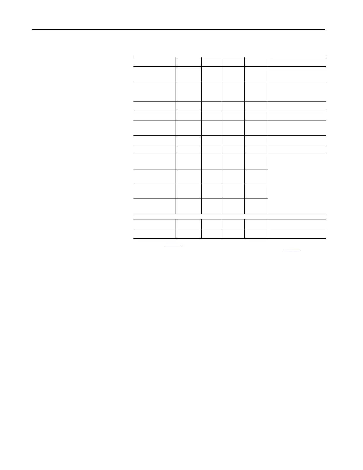
Table 33 - PowerFlex 700S Main Control Board Switch and Jumper Assignment
Function Default Switch Open Closed Notes
HW Enable Jumper
(P22)
pins 2-4
HW Enbl
SHUNT
Jumper
pins 2-4
HW Enbl
pins 1-3
No Enbl
No Jmpr = HW Enbl.
Gate Enable Jumper
(P13)
Jumper on
pins 15-16
SHUNT
Jumper
No Jmpr Jumper on
pins 15-16
No Jmpr = Gate disable or Safe-
Off/Second Encoder board is
present
(1)
(1) See publication 20D-UM007, DriveGuard® Safe Torque Off Option for PowerFlex 700S Phase II AC Drives and PowerFlex 700L
Liquid-Cooled AC Drives, for more information on the Safe Torque Off Option board, or publication, 20D-IN009
Installation
Instructions - Second Encoder Option Card for PowerFlex 700S Drives with Phase II Control, for more information on the Second
Encoder Option board.
Analog Input 1 Voltage S5-2 Voltage Current Change with Power Off
Analog Input 2 Voltage S5-1 Voltage Current Change with Power Off
Digital Inputs 4-6
Voltage
24V DC S4-1,
S4-2
115V AC 24V DC Change with Power Off
Digital Input 1 Voltage 24V DC S3-1 24V DC 12V DC Change with Power Off
Digital Input 2 Voltage 24V DC S3-2 24V DC 12V DC Change with Power Off
Encoder Supply
Voltage
12V DC S2-4 12V DC 5V DC Change with Power Off
Typically, set all switches the
same
Encoder Signal A
Voltage
12V DC S2-1 12V DC 5V DC
Encoder Signal B
Voltage
12V DC S2-2 12V DC 5V DC
Encoder Signal Z
Voltage
12V DC S2-3 12V DC 5V DC
Function Switch Down Up Center Notes
DriveLogix Processor S1 RUN PROG REMOTE Processor Mode
 Loading...


