Rockwell Automation Publication 750-RM004A-EN-P - April 2018 69
Selection Considerations Chapter 1
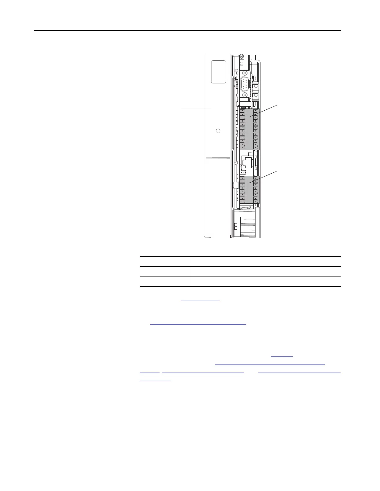
Figure 10 - PowerFlex 700S Main Control Board I/O Connector Locations
See publication PFLEX-IN006 for I/O connector wiring and analog
configuration jumpers.
See Hardware Enable Circuits
on page 74 for information on using Hardware
Enable.
The PowerFlex 700S could be equipped with several communication and
feedback options. Not all devices that are shown in Ta ble 3 5
have equivalent
PowerFlex 755T devices. See Specification and Features Comparison
on
page 35, Drive Configuration on page 89, and Communication Configuration
on page 113 for more information about compatible PowerFlex 755T devices.
TB1 Terminals
TB2 Terminals
Control
Cassette
Table 34 - PowerFlex 700S Main Control Board I/O Connections
Connector Description
TB1 Analog I/O and Encoder Signals
TB2 Digital I/O
 Loading...


