General Installation Information 1-5
of standard shielded cable and also combines considerable mechanical
strength and resistance to moisture. It can be installed in concealed and
exposed manners and removes the requirement for conduit (EMT) in the
installation. It can also be directly buried or embedded in concrete.
Because noise containment can be affected by incidental grounding of the
armor to building steel (see Chapter 2. “Wire Types,” of publication
Drives-IN001, Wiring and Grounding Guidelines for Pulse Width
Modulated (PWM) AC Drives) when the cable is mounted, it is
recommended the armored cable have an overall PVC jacket.
Interlocked armor is acceptable for shorter cable runs, but continuous
welded armor is preferred.
Best performance is achieved with 3 spaced ground conductors, but
acceptable performance below 200 HP is provided via a single ground
conductor.
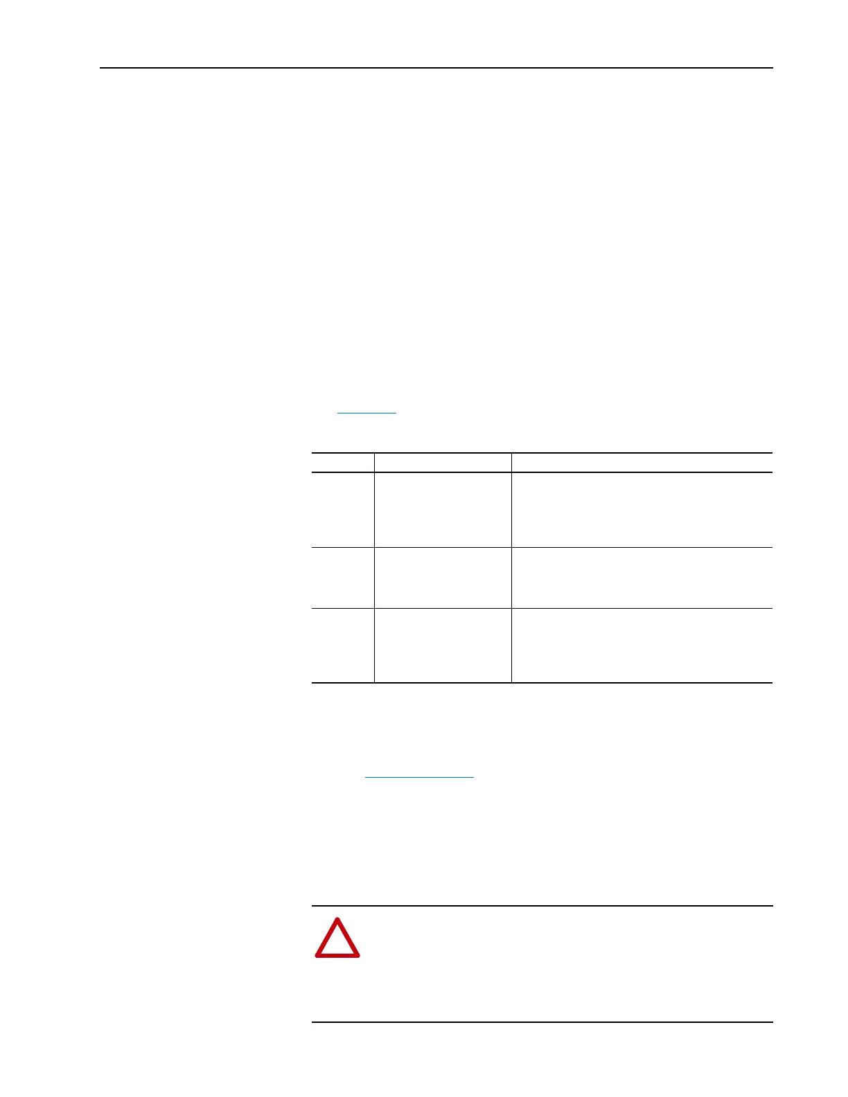
See Table 1.B
.
Table 1.B Recommended Shielded / Armored Cable
EMC Compliance
Refer to EMC Instructions for details.
CabIe Trays and Conduit
If cable trays or large conduits are to be used, refer to guidelines presented
in the PowerFlex Reference Manual.
Location Rating/Type Description
Standard
(Option 1)
600V, 90° C (194° F)
XHHW2/RHW-2
Anixter B209500-B209507,
Belden 29501-29507, or
equivalent
• Four tinned copper conductors with XLPE insulation.
• Copper braid/aluminum foil combination shield and
tinned copper drain wire.
• PVC jacket.
Standard
(Option 2)
Tray rated 600V, 90° C (194°
F) RHH/RHW-2
Anixter OLF-7xxxxx or
equivalent
• Three tinned copper conductors with XLPE insulation.
• 5 mil single helical copper tape (25% overlap min.) with
three bare copper grounds in contact with shield.
• PVC jacket.
Class I & II;
Division I & II
Tray rated 600V, 90° C (194°
F) RHH/RHW-2
Anixter 7V-7xxxx-3G or
equivalent
• Three bare copper conductors with XLPE insulation
and impervious corrugated continuously welded
aluminum armor.
• Black sunlight resistant PVC jacket overall.
• Three copper grounds on #10 AWG and smaller.
!
ATTENTION: To avoid a possible shock hazard caused by
induced voltages, unused wires in the conduit must be grounded
at both ends. For the same reason, if a drive sharing a conduit is
being serviced or installed, all drives using this conduit should be
disabled. This will help minimize the possible shock hazard from
“cross coupled” motor leads.
 Loading...


