PowerFlex 700S Control Wiring 3-3
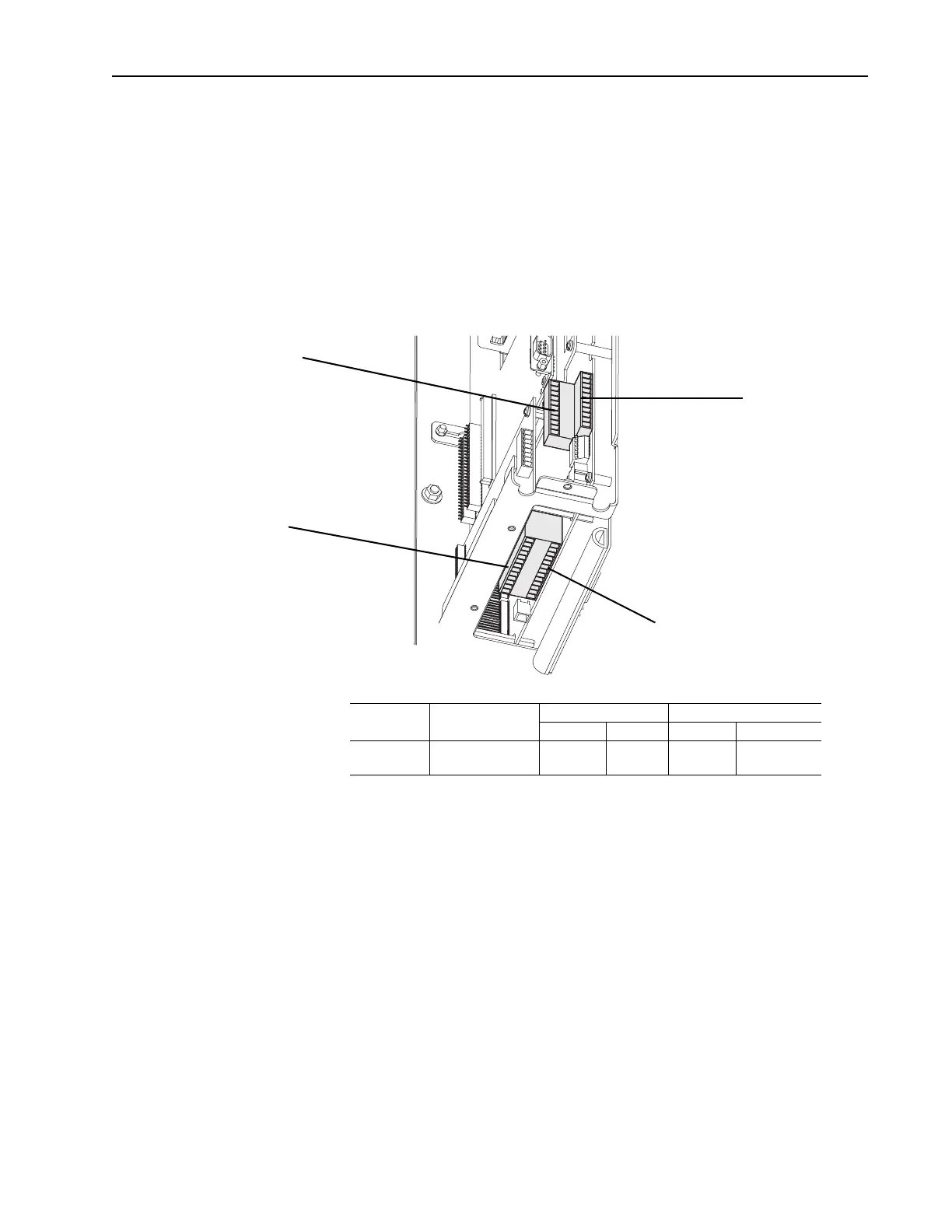
Wiring the Main Control Board I/O Terminals
Terminal blocks TB1 and TB2 contain connection points for all inputs,
outputs and standard encoder connections. Both terminal blocks reside on
the Main Control Board.
Remove the terminal block plug from the socket, and make connections.
Reinstall the plug, when wiring is complete. The terminal blocks have keys,
which make it difficult to insert a terminal plug into the wrong socket.
Table 3.B Main Control Board I/O Terminal Locations
Table 3.C Main Control Board I/O Terminal Block Specifications
TB1
TB2
TB1 - Row T (Top)
TB1 - Row B (Bottom)
TB2 - Row T (Top)
TB2 - Row B (Bottom)
Name Description
Wires Size Range
(1)
(1)
Maximum/minimum sizes the terminal block will accepts - these are not recommendations.
Torque
Maximum Minimum Maximum Recommended
I/O & Encoder
Blocks
Signal & Encoder
power connections
1.5 mm
2
(16 AWG)
.14 mm
2
(28 AWG)
.25 N-m
(2.2 lb.-in.)
.22 N-m
(1.9 lb.-in.)
 Loading...


