3-4 PowerFlex 700S Control Wiring
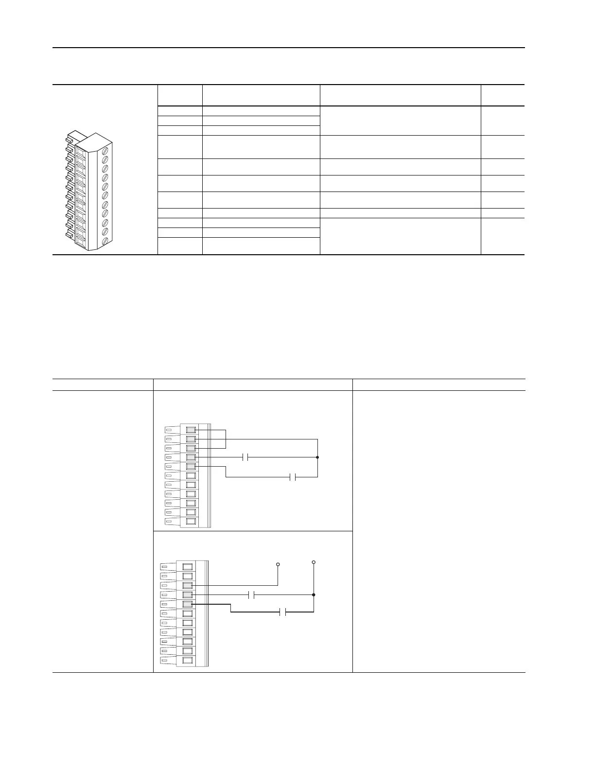
Table 3.D TB1 - Row T (Top) Terminals
Terminal Signal Description
Related
Parameter
T11 Power Supply 24V dc Return (-) Power and common for pre charge and enable inputs.
(1)
Inputs
may sink or source.
(2)
Rating: 100 mA maximum.
T10 Power Supply 24V dc (+)
T9 Logic Common
T8 Digital Input #1
Default = Precharge
For common DC bus drives. Must be high, for drive to complete
the pre charge cycle.
Load: 20 mA at 24V dc.
824, 826, 827,
828, 829, 838
T7 Enable Input Must be high for drive to run.
Load: 20 mA at 24V dc.
824, 825
T6 Digital Output #1 24V dc open collector (sinking logic) output.
Rating: 25 mA maximum.
824, 843, 844
T5 Digital Output #2 24V dc open collector (sinking logic) output.
Rating: 25 mA maximum.
824, 845, 846
T4 Digital Output Return Return for Digital outputs 1 and 2.
T3 Thermistor Input Used only in FOC2 mode with approved motor for temperature
adaptation.
Refer to Appendix A, “Supplemental Information”, in publication
20D-UM001, User Manual - PowerFlex 700S High Performance
AC Drive, for approved motors.
485
T2 Thermistor Input Return
T1 Thermistor Shield
(1)
The drive’s 24V dc power supply supports only on-board digital inputs. Do not use it to power circuits outside of the drive.
(2)
Refer to wiring examples of sinking and sourcing outputs.
1110
9
8
7
6
5
43T1 2
Figure 3.1 TB1 - Row T (Top) Wiring Examples
The following definitions are used throughout this section:
Source
A. Apply positive voltage through the device to the input or output.
B. Connect the input or output common (return) directly to the power supply common.
Sinking
A. Apply the positive voltage directly to the input or output common (return).
B. Connect the input or output to the power supply common through the device
Input/Output Connection Example Required Parameter Changes
Digital Inputs used for enable
and precharge control.
Note:
24V dc Supply - supports
only on-board digital inputs.
Do not use for circuits outside
the drive.
Sourcing Precharge and Enable Inputs - using internal power
supply
Enable - In sourcing configuration. this circuit must
connect to 24V dc power for drive to run.
Precharge
Precharge control is used in common bus
configurations and is not required for AC fed drives.
If precharge control is not required, reprogram Par
838 [DigIn 1 Sel] to a value of zero or replace the
contact shown with a jumper from Terminal 8 to
Terminal 10.
If precharge is needed, in sourcing configuration, this
circuit must connect to 24V dc power for drive to
complete the precharge cycle.
Sourcing Precharge and Enable Inputs - using external power
11
10
9
8
7
Precharge
Enable
9
8
7
Precharge
Enable
+24V dc
Common
(Return)
 Loading...


