PowerFlex 700S Control Wiring 3-5
Input/Output Connection Example Required Parameter Changes
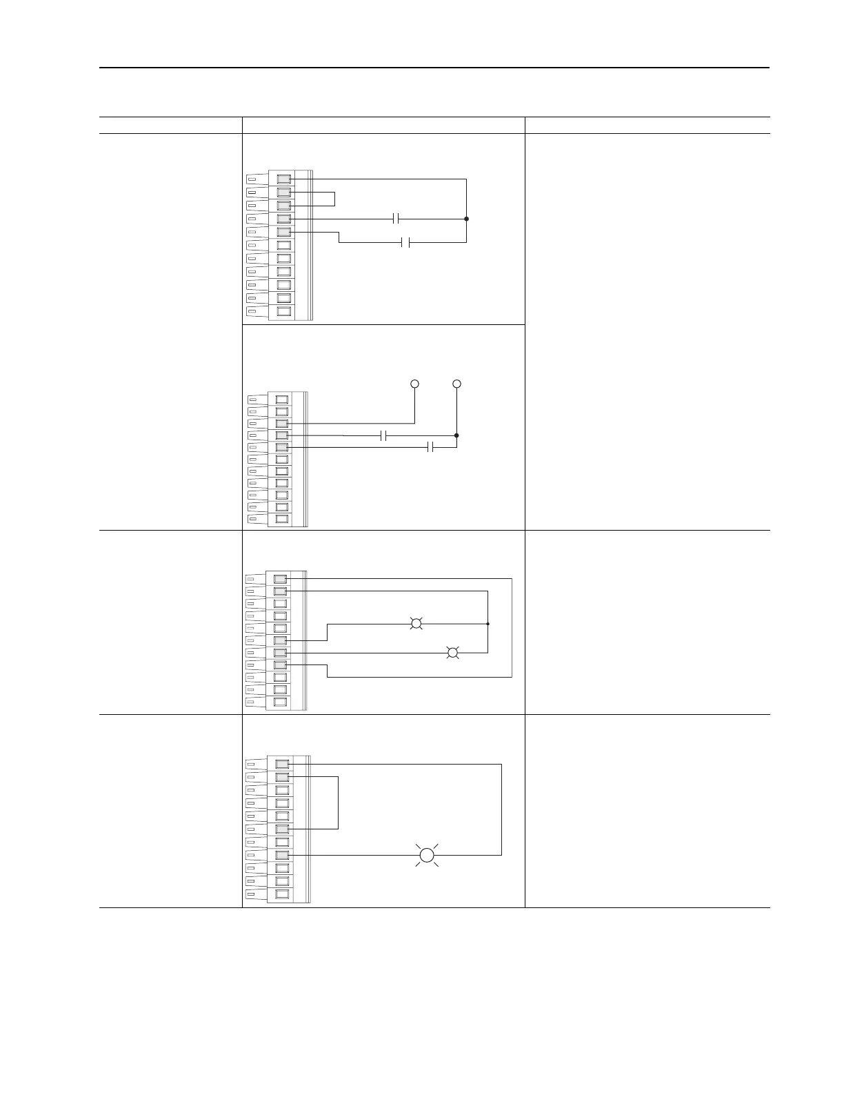
Sinking Precharge and Enable Inputs - using internal power
supply
Enable - In sinking configuration. this circuit must
connect to 24V dc return for drive to run.
Precharge
Precharge control is used in common bus
configurations and is not required for AC fed drives.
If precharge control is not required, reprogram Par
838 [DigIn 1 Sel] to a value of zero or replace the
contact shown with a jumper from Terminal 8 to
Terminal 11.
If precharge is needed, in sinking configuration, this
circuit must connect to 24V dc return for drive to
complete the precharge cycle.
Sinking Precharge and Enable Inputs - using external power
supply
Digital Outputs - 24V dc
outputs 25 mA maximum per
output
Digital Output 1 Indicating Alarm and Digital Output 2
Indicating Fault - in sourcing configuration
Example: Using Digital Outputs 1 and 2 to
Annunciate Alarms and Faults
• Link Parameter 155 [Logic Status], the source, to
Parameter 843 [DigOut 1 Data], the sink
• Set Parameter 844 [DigOut 1 Bit] to a value of
eight, so that parameter 155 [Logic Status] / bit 8
“Alarm” will control the output
• Link Parameter 155 [Logic Status], the source, to
Parameter 845 [DigOut 2 Data], the sink
• Set Parameter 846 [DigOut 2 Bit] to a value of
seven, so that Parameter 155 [Logic Status] / bit 7
[Faulted] will control the output
Digital Output - 24V dc
output 25 mA maximum per
output.
If one (1) output is configured
in sinking, the other output is
not available.
Digital Output 1 Indicating Alarm Fault - in sinking
configuration
Example: Using Digital Outputs 1 to Annunciate
Alarms
• Link Parameter 155 [Logic Status], the source, to
Parameter 843 [DigOut 1 Data], the sink
• Set Parameter 844 [DigOut 1 Bit] to a value of 8, so
that Parameter 155 [Logic Status] / bit 8 “Alarm”
will control the output
Figure 3.1 TB1 - Row T (Top) Wiring Examples
11
10
9
8
7
Precharge
Enable
+24V DC
Common
(Return)
9
8
7
Precharge
Enable
6
5
4
11
10
Alarm
Fault
6
4
11
10
Alarm
 Loading...


