3-6 PowerFlex 700S Control Wiring
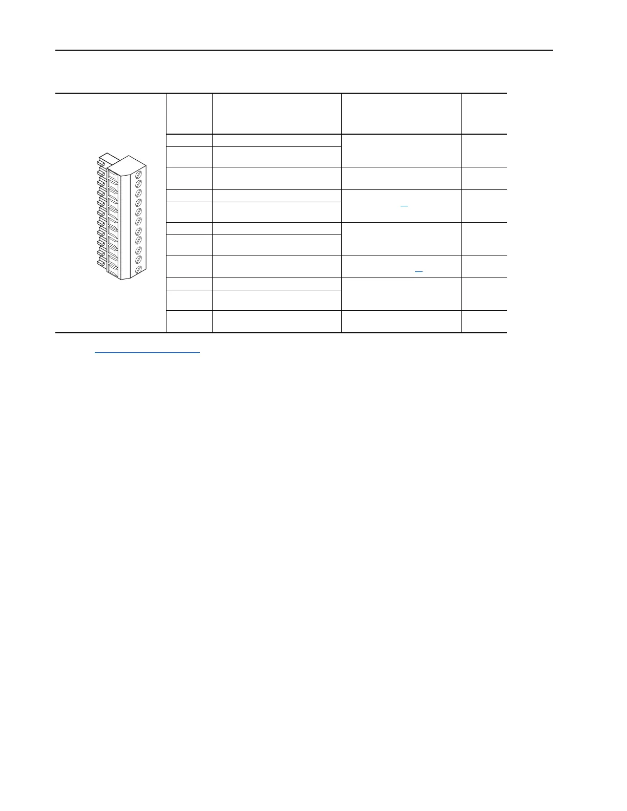
Table 3.E TB1 - Row B (Bottom) Terminals
Terminal Signal Description
Related
Parameter
B11 Analog Input #1 (-) +/-10.0V dc or +/-1.0V dc bipolar,
differential input.
(1)
13 bit + sign,
20k ohm input impedance
800, 802,
803, 804,
805
B10 Analog Input #1 (+)
B9 Analog Input Shield Optional connection point for
analog input shield.
(2)
B8 Analog Input #2 (-) +/-10.0V dc or +/-1.0V dc bipolar,
differential input.
(1)
13 bit + sign,
20k ohm input impedance
806, 808,
809, 810,
811
B7 Analog Input #2 (+)
B6 Analog Output #1 (+) +/-10.0V dc bipolar, differential
output, 11 bit + sign, 2k ohm
minimum load
812, 814,
815, 817,
818
B5 Analog Output #1 Return (-)
B4 Analog Output Shield Optional connection point for
analog output shield.
(2)
B3 Analog Output #2 (+) +/-10.0V dc bipolar, differential
output, 11 bit + sign, 2k ohm
minimum load
813, 819,
820, 822,
823,
B2 Analog Output #2 Return (-)
B1 Analog Output Shield Optional connection point for
analog shields.
(1)
Refer to Analog Input Settings on page 3-16 for necessary dip switch settings.
(2)
Analog shields should connect to common at the signal source, if possible. Shields for signals from ungrounded devices, such as analog
tachometers, should connect to an analog shield terminal point at the drive.
1110
9
8
7
6
5
43B1 2
 Loading...


