PowerFlex 700S Control Wiring 3-7
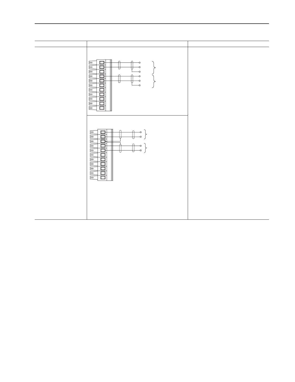
Figure 3.2 TB1 - Row B (Bottom) Wiring Examples
Input/Output Connection Example Required Parameter Changes
Analog Inputs
+/-10V dc or +/-1.0V dc
(DIP switch selectable)
Terminate shields at the analog
source if analog common is
available
Used for Speed Reference and
Speed Trim
Analog Inputs for Speed Reference and Speed Trim - shield
terminated at source
Example: Using Analog In1 as 0-10V speed
reference
• Adjust Parameter 803 [Anlg In1 Offset] so that
the minimum analog signal creates the
minimum speed reference (if the minimum input
is 0V dc and the minimum speed reference is
zero, enter a value of zero)
• Adjust the Parameter 802 [Anlg In1 Offset] so
that the maximum analog signal creates the
maximum speed reference (if the maximum
input is 10V dc and the maximum speed
reference is motor base speed, enter a value of
0.1)
• Send the data to the Speed Reference
parameter
Par 10 [Speed Ref1] (the destination) linked to
Par 800 [Anlg In1 Data] (the source)
• Select Ref 1 as the active speed ref Par 16
[Speed Ref Sel] = 1
• Par 153 [Control Option]/bit 0 = 0 Unipolar
Speed Reference”
Example: Using Analog In2 as -10 to +10V
speed trim @ 10%:
• Adjust Parameter 809 [Anlg In2 Offset] so that
the minimum analog signal creates the
minimum speed trim (if the minimum input is 0V
dc and the minimum trim is zero, enter a value
of zero)
• Adjust Parameter 808 [Anlg In2 Offset] so that
the maximum analog signal creates the
maximum speed trim (if the maximum input is
10V dc and the maximum speed trim is 10%,
enter a value of 0.01)
• Send the data to the speed Reference
parameter
Par 13 [Speed Ref2] (the destination) linked to
Par 806 [Anlg In2 Data] (the source)
• Select Ref 1 as the active speed ref and Ref2
as trim [Speed Ref Sel] = 3
Analog Inputs for Speed Reference and Speed Trim - shield
terminated at drive
11
10
8
7
-
+
Common
(Return)
Analog Input #1
Speed
Reference
-
+
Common
(Return)
Analog Input #2
Speed
Tr im
11
10
8
7
-
+
Analog Input #1
Speed
Reference
-
+
Analog Input #2
Speed
Tr im
 Loading...


