PowerFlex 700S Control Wiring 3-9
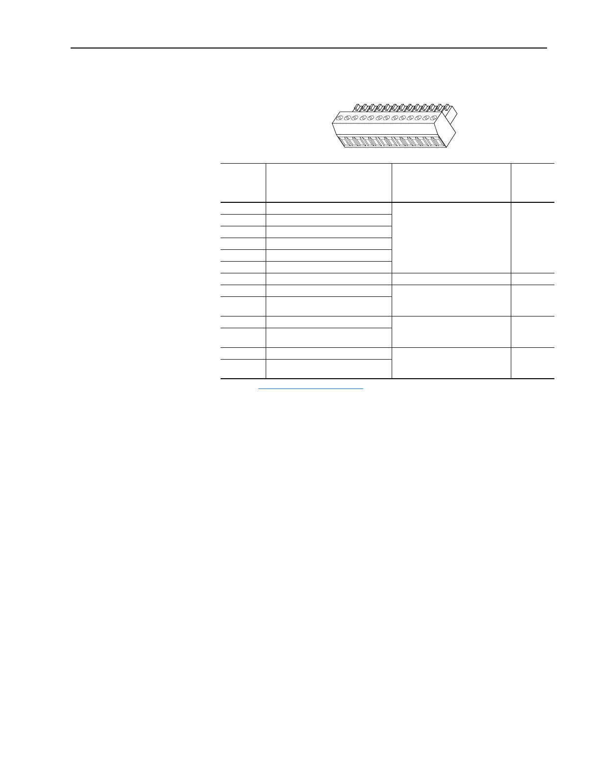
Table 3.F TB2 - Row T (Top) Terminals
Terminal Signal Description
Related
Parameter
T13 Encoder Signal A Primary encoder interface. 5 or 12V
dc switch selectable
(1)
, Nominal
current draw per channel @ 12V dc
45 mA, @5V dc 32 mA
Maximum input frequency for
Encoders 0 & 1 is 500 kHz.
(1)
Refer to Encoder Input Settings on page 3-16 for necessary dip switch settings.
222, 230,
231, 232,
233, 234,
235, 236,
237, 238
T12 Encoder Signal Not A
T11 Encoder Signal B
T10 Encoder Signal Not B
T9 Encoder Signal Z
T8 Encoder Signal Not Z
T7 Shield Connection point for encoder shield.
T6 Digital Input #2 High speed 12-24V dc sinking
digital input.
824, 830,
831, 832,
833, 839
T5 Digital Input #2 Return
T4 Digital Input #3 High speed 12-24V dc sinking
digital input.
824, 834,
835, 836,
837, 840
T3 Digital Input #3 Return
T2 Power Supply +12V dc (A) (+) 5/12V dc power supply for primary
encoder interface and high speed
inputs. Rating 300 mA
(2)
(3)
(2)
This power supply supports only the primary encoder interface and digital inputs. Do not use it to power circuits
outside of the drive.
(3)
To enable 5V supply, set Jumper J6 (located in the Main Control Board) to positions T2 and T3. Default 12V
supply is set to T1 and T2.
T1 Power Supply +12V dc Return (A) (-)
T1
2
3
4
5
6
7
8
9
10
11
12
13
 Loading...


