3-10 PowerFlex 700S Control Wiring
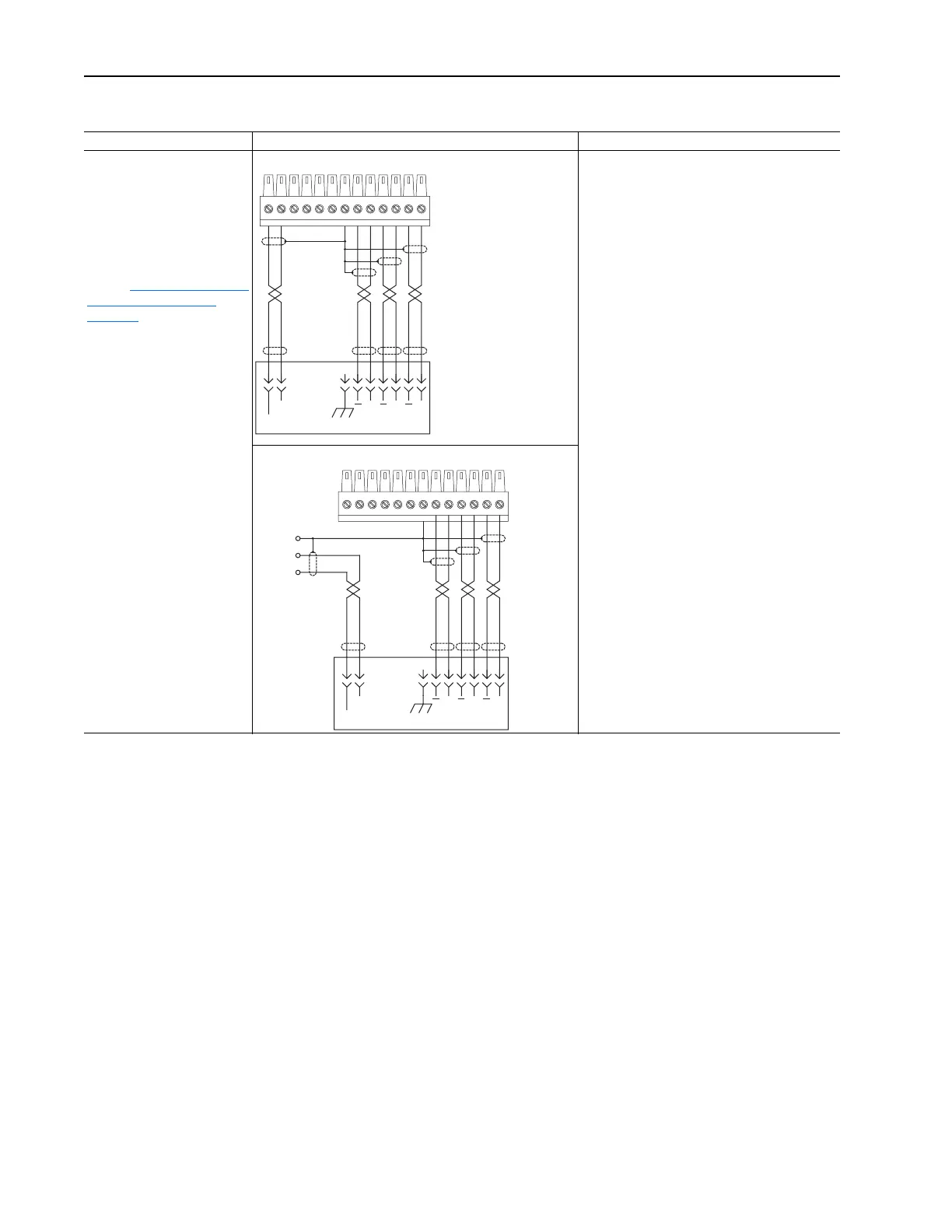
Figure 3.3 TB2 - Row T (Top) Wiring Examples
Input/Output Connection Examples Required Parameter Changes
Primary Encoder Interface -
Supports 12V dc differential
encoders with internal power
supply.
5V dc differential encoders may
require external power supply
and special jumper settings.
Refer to Main Control Board I/O
and Encoder Settings on
page 3-16 for external power
supply and jumper settings.
For 5V dc differential encoders
with internal power supply, set
Jumper J6 to positions T2 and
T3.
Primary Encoder - using internal power supply Example: Using Encoder 0 for Primary Motor
Speed Feedback
• Set the value of Parameter 222 [Motor Fdbk
Sel] to a value of 0 - Encoder 0, so the drive will
use this encoder as the primary motor speed
feedback device.
• Set the value of Parameter 232 [Encoder0 PPR]
to match the encoder’s resolution.
Primary Encoder - using external power supply
1312111098721
Power
Common
(Return)
AA
BBZZ
Case Ground
13121110987
Power
Common
(Return)
AA
BBZZ
Case Ground
Shield
Power
Common
(Return)
 Loading...


