4-4 Communication Options
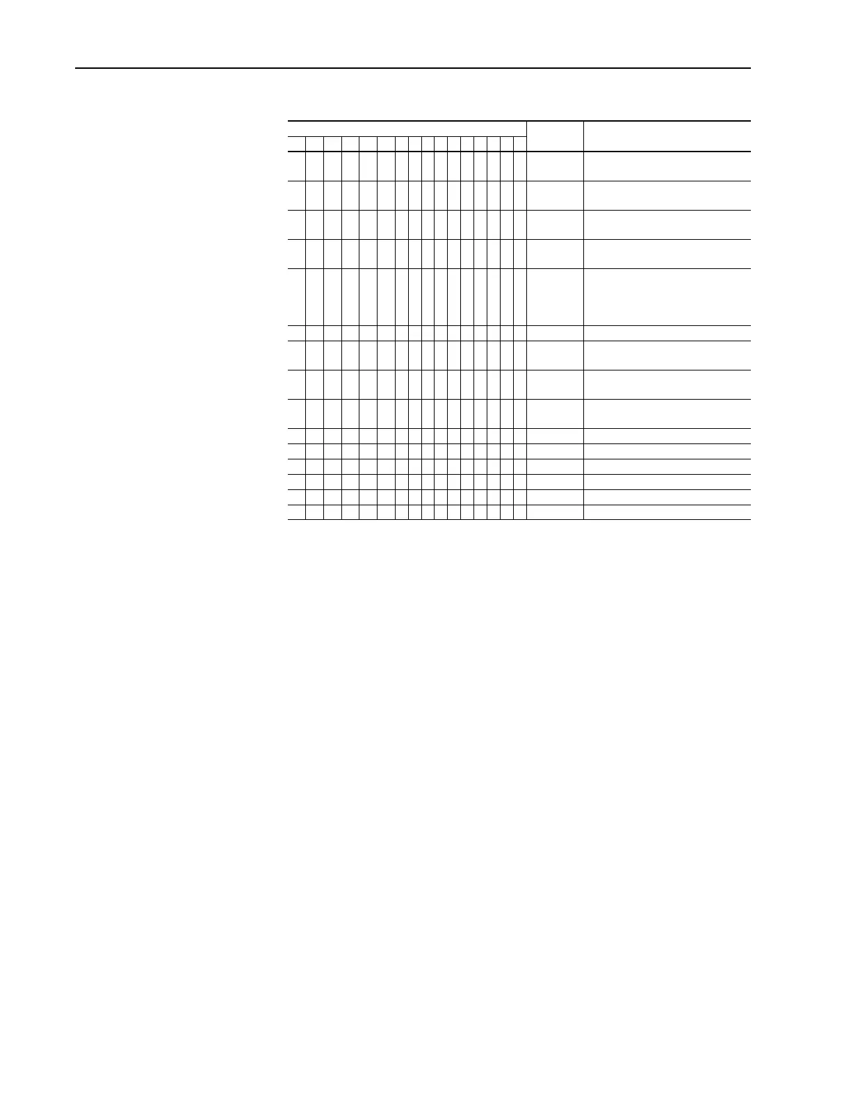
Figure 4.4 PowerFlex 700S Logic Command Word
Logic Bits
15 14 13 12 11 10 9 8 7 6 5 4 3 2 1 0 Command Description
xNormal
Stop
0 = Not Normal Stop
1 = Normal Stop
xStart
(1)
(1)
A Not Stop condition (logic bit 0 = 0, logic bit 8 = 0, and logic bit 9 = 0) must first be present before a 1 = Start
condition will start the drive.
0 = Not Start
1 = Start
x Jog 1 0 = Not Jog using [Jog Speed 1]
1 = Jog using [Jog Speed 1]
xClear
Fault
(2)
(2)
To perform this command, the value must switch from “0” to “1.”
0 = Not Clear Fault
1 = Clear Fault
x x Unipolar
Direction
00 = No Command
01 = Forward Command
10 = Reverse Command
11 = Hold Direction Control
x Reserved
x Jog 2 0 = Not Jog using [Jog Speed 2]
1 = Jog using [Jog Speed 2]
x Current
Limit Stop
0 = Not Current Limit Stop
1 = Current Limit Stop
x Coast Stop 0 = Not Coast to Stop
1 = Coast to Stop
x Reserved
x Reserved
x Reserved
x Reserved
x Reserved
x Reserved
Table 0.A
 Loading...


