6-2 Frame 10 Installation
Enclosed Lifting Instructions
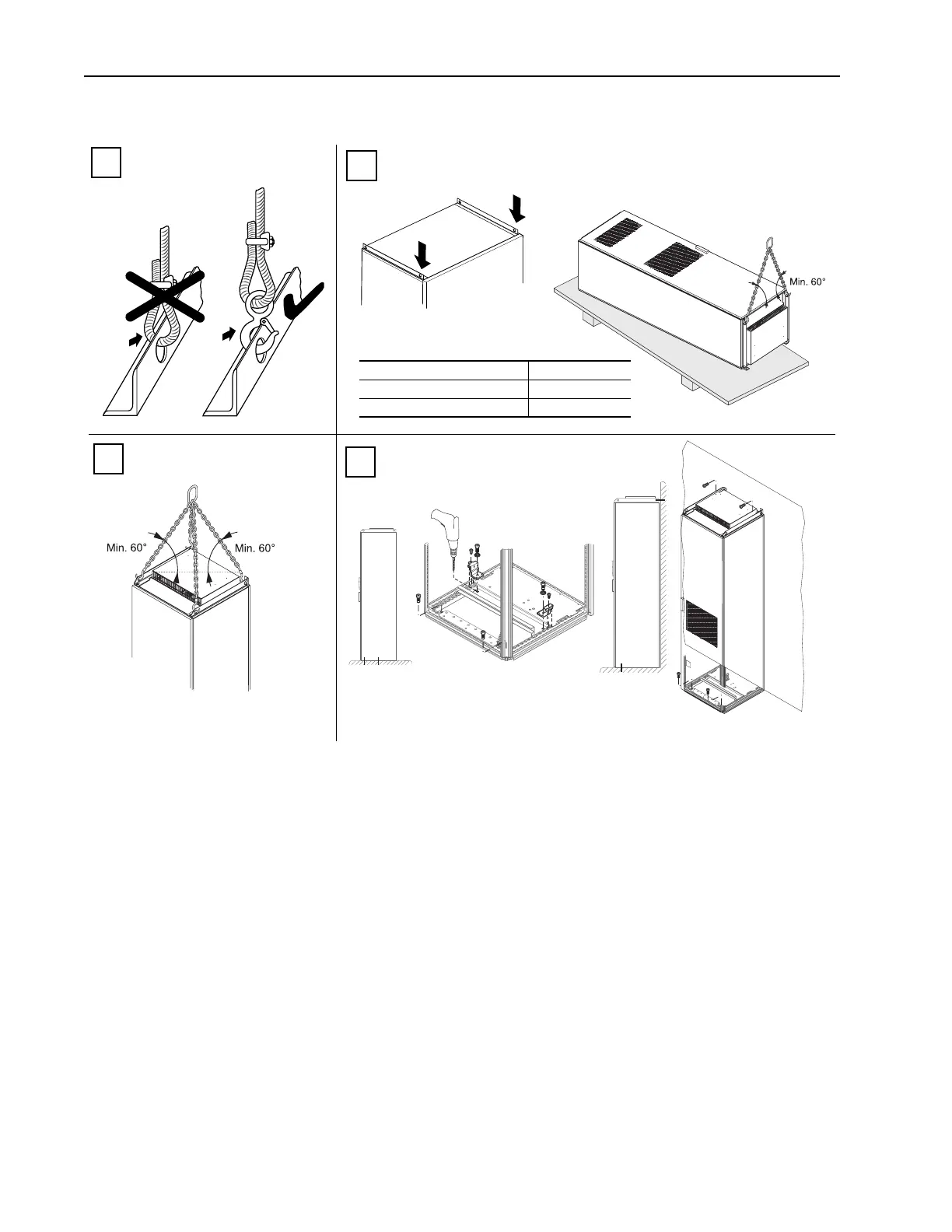
1
2
3
wall
Use the front two holes to lift the enclosure upright.
Type Weight kg (lbs.)
Drive & Enclosure (AC Input) 480 (1056)
Drive & Enclosure (DC Input) 365 (802)
Use four holes to position the enclosure.
The angle between the enclosure and
lifting wire must be 60° or more.
4
Wall Mounting: Secure drive to the floor with
anchor bolts in the front corner holes of the
enclosure base plate. Secure the drive by
bolting the adjustable lifting rails to the rear
wall or supporting structure.
Floor Only Mounting: Secure drive to the floor
with anchor bolts in the front corner holes of the
enclosure base plate. Additionally secure the
drive using the mounting plates as needed (Rittal
part no. 8800-210 or equivalent). Do this as far
back as possible to the choke assembly plate.
With this method the holes through base plate
must be drilled on-site.
 Loading...


