Preparing for Use
R&S
®
NRPxxA(N)
16User Manual 1177.6017.02 ─ 05
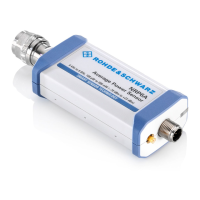
Setup
NRP
3-Path Diode Power Sensor
MHz to GHz, 100 pW to 200 mW (−70 dBm to +23 dBm)
SMART SENSOR TECHNOLOGY
Figure 3-1: Setup with an R&S NRP
‑
ZKU cable
1 = Signal source
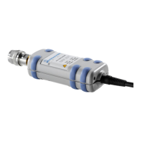
2 = R&S NRPxxA(N) power sensor
3 = Host interface connector
4 = R&S NRP‑ZKU cable
5 = USB connector
6 = Computer with installed VISA driver or R&S NRP Toolkit
Incorrectly connecting/disconnecting the R&S NRPxxA(N) power sensors can damage
the power sensors or lead to erroneous results.
Ensure that you connect/disconnect your power sensor as described in Chapter 3,
"Preparing for Use", on page 13.
1. Connect the cables as shown in Figure 3-1 :
a) Connect the R&S NRP‑ZKU cable to the power sensor.
b) Connect the R&S NRP‑ZKU cable to the computer.
c) Connect the power sensor to the signal source.
2. On the computer, start a software application to view the measurement results.
See Chapter 5, "Operating Concepts", on page 29.
3.5.1.2 R&S NRP‑Z5 Sensor Hub Setup
The R&S NRP‑Z5 sensor hub (high-speed USB 2.0) can host up to four R&S
NRPxxA(N) power sensors and provides simultaneous external triggering to all con-
nected sensors.
Required equipment
●
1 to 4 R&S NRPxxA(N) power sensors
●
1 R&S NRP‑ZK6 cable per sensor
●
R&S NRP‑Z5 sensor hub with external power supply unit and USB cable
●
BNC cables to connect the trigger input and trigger output signals (optional)
Connecting to a Computer

 Loading...