Power Sensor Tour
R&S
®
NRPxxA(N)
26User Manual 1177.6017.02 ─ 05
Table 4-1: R&S
NRPxxA(N) RF connector characteristics
Power sensor Matching female con-
nector
Male connector Tightening torque
R&S NRP6A
N N 1.36 Nm (12'' lbs)
R&S NRP6AN
R&S NRP18A
R&S NRP18AN
4.2 Trigger I/O Connector
The trigger I/O is a connector of SMB type.
It is used as an input for signals if the trigger source parameter is set to EXTernal2. It
is used as an output for trigger signals if the sensor is operated in the trigger master
mode.
Further information:
●
Chapter 9.5.2, "Triggering", on page 72
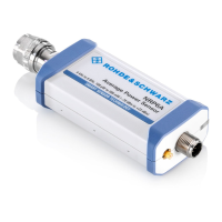
4.3 Host Interface
The host interface connector is used for establishing a connection between the power
sensors and a USB host or a supported Rohde & Schwarz instrument. For this pur-
pose, an external cable is needed. Two types of cables are available:
●
R&S NRP‑ZKU cable with a USB connector, for connecting the power sensor to a
USB host device (R&S order number 1419.0658.xx).
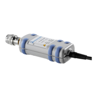
●
R&S NRP‑ZK6 cable with a push-pull type connector, for connecting the power
sensor to a base unit, R&S NRX or R&S NRP2, or other Rohde & Schwarz prod-
ucts with the round connector (R&S order number 1419.0664.xx).
These cables can be obtained in different lengths up to 5 meters.
4.4 Status LED
The status LED gives information about the state of the power sensor. The following
states are defined:
Indication State
White Idle state. The sensor performs no measurement and is ready for use.
Flashing white Firmware update is in progress
Status LED

 Loading...