Preparing for Use
R&S
®
NRPxxA(N)
19User Manual 1177.6017.02 ─ 05
Setup with a PoE Ethernet switch
Ethernet Switch
(PoE)
1
4
6
5
2
3
HOST
INTERFACE
IN: 3 V or 5 V logic
OUT: min. 2 V into 50 Ω
max. 5.3 V
TRIG2
I/0
PoE
SMART SENSOR TECHNOLOGY
NRP
7
Figure 3-3: Setup with a PoE Ethernet switch
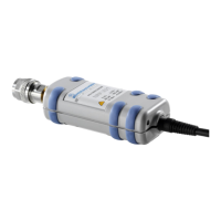
1 = Signal source
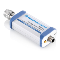
2 = LAN power sensor
3 = RJ-45 Ethernet connector
4, 6 = RJ-45 Ethernet cable
5 = Ethernet switch supporting PoE power delivery, e.g. R&S NRP-ZAP1
7 = Computer
1. Connect the [RF] connector of the sensor to the DUT.
2.
NOTICE! Risk of sensor damage. Use only PoE power sourcing equipment (PSE)
according to IEEE standards 802.3af or IEEE 802.3at.
Otherwise your power sensor can get damaged.
Connect the RJ-45 Ethernet connector of the sensor to an Ethernet switch that
supports PoE power delivery.
3. Connect the computer to the Ethernet switch.
4. Establish a connection between the power sensor and the network.
See Chapter 3.5.2.2, "Establishing a Connection to the Network", on page 21.
Connecting to a Computer

 Loading...