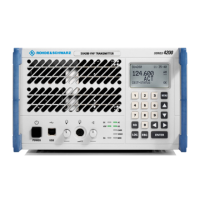
R&S SU 4200 Interface Description
6125.0226.12.01 6.2
6.2.2 DC Input/Battery Input X2
XLR connector type
Fig. 6.2 DC input/battery input X2
Entry in column D (direction): O = Output I = Input B = Bi-directional
Entry in column T (type): A = Analog D = Digital P = Power
Signal description D T Range Contact Remarks
Battery I P X2.1 Positive battery contact
GND I P
19 to 32 V DC
max. 16 A
(if an external device
is connected to X5.6,
X7.1/X7.2, X10.6 and
X11.1/ X11.2)
X2.2 Negative battery contact
System ground
N.C. – – – X2.3 N. C.
Common Antenna X3 \Commo n Antenna X3 "Radi o".doc
1
3
2

 Loading...