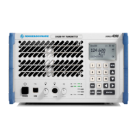
Specifications R&S SU 4200
6.1 6125.0226.12.01
6 Technical Information
This chapter
This chapter contains a description of the transmitter interfaces.
Further
information
Chapter
3.1 contains an overview of transmitter control elements,
indicators, etc.
Chapter
3 describes how to put the radio into operation.
6.1 Specifications
Note: See Specifications in the Appendix.
6.2 Interface Description
Note: Signal names with a leading "/" are low-active (e.g. /TEST_OC).
6.2.1 AC Input X1
Power entry module
Fig. 6.1 AC input X1
Entry in column D (direction): O = Output I = Input B = Bi-directional
Entry in column T (type): A = Analog D = Digital P = Power
Signal description D T Range Contact Remarks
L I P X1.L Main power – phase
N I P
115 V/230 V AC
–10/+15 %
47 to 63 Hz
max. 400 W
X1.N Main power – neutral
E I P Safety ground X1.E Safety ground
N
E
L

 Loading...