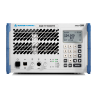
Interface Description R&S SU 4200
6.7 6125.0226.12.01
6.2.7 TX Audio Extended X7
DSUB male (15 pins)
Fig. 6.7 TX audio extended X7
Entry in column D (direction): O = Output I = Input B = Bi-directional
Entry in column T (type): A = Analog D = Digital P = Power
Signal description D T Range Contact Remarks
+28 V O P X7.1
+28 V O P
19 to 32 V
X7.2
DC supply for external
filter (external device)
Max. 2 A (peak 4 A)
protected PTC
Note: Maximum current in
sum with X5.6
GND B P Ground X7.3
GND B P Ground X7.4
/CARRIER O D Low = carrier > 0.5 W
Open collector
Ri = 220
limited to max. 6.8 V
X7.5 Indicates that
RF antenna power
approx. 500 mW
Corresponds to CARR
LED on front panel
/VSWR O D Low = VSWR > 2
Open collector
Ri = 220
limited to max. 6.8 V
X7.6 Corresponds to VSWR
LED on front panel
/TX_INHIBIT I D Contact against
ground (low) = inhibit
transmission
Internal pull-up 10 k
to 3.3 V, limited to
max. 6.8 V
X7.7
EXT_VSWR I A 0 to 5 V
limited to max. 6.8 V
R
L
= 17 k
X7.8 Used e.g. for monitoring of
external RF detector
Generates CBIT warning
when the configurable
threshold voltage value is
exceeded during TX
GND B P Ground X7.9
SER_CONTR_TXD_A O D RS-422/RS-485 X7.10 RS-422/RS-485
8
1
9
15

 Loading...