86
MFX/IFX Parameters
03 Isolator
This is an equalizer which cuts the volume greatly, allowing you to add
a special eect to the sound by cutting the volume in varying ranges.
L in L out
R outR in
Parameter Value Explanation
Boost/Cut Low -60–+4 [dB]
These boost and cut each of the High, Middle,
and Low frequency ranges.
At -60 dB, the sound becomes inaudible. 0 dB
is equivalent to the input level of the sound.
Boost/Cut Mid -60–+4 [dB]
Boost/Cut High -60–+4 [dB]
Anti Phase Low Sw OFF, ON
Turns the Anti-Phase function on and o for
the Low frequency ranges.
When turned on, the counter-channel of
stereo sound is inverted and added to the
signal.
Anti Phase Low Level 0–127
Level of the Anti-Phase function for the Low
frequency ranges.
Adjusting this level for certain frequencies
allows you to lend emphasis to specic parts.
(This is eective only for stereo source.)
Anti Phase Mid Sw OFF, ON Settings of the Anti-Phase function for the
Middle frequency ranges.
The parameters are the same as for the Low
frequency ranges.
Anti Phase Mid Level 0–127
Low Boost Sw OFF, ON
Turns Low Booster on/o.
This emphasizes the bottom to create a heavy
bass sound.
Low Boost Level 0–127
Increasing this value gives you a heavier low
end.
Depending on the Isolator and lter settings
this eect may be hard to distinguish.
Level 0–127 Output Level
04 Low Boost
Boosts the volume of the lower range, creating powerful lows.
L in L out
R outR in
Parameter Value Explanation
Boost
Frequency
50, 56, 63, 71, 80, 90,
100, 112, 125 [Hz]
Center frequency at which the lower range
will be boosted
Boost Gain 0–+12 [dB]
Center frequency at which the lower range
will be boosted
Boost Width WIDE, MID, NARROW Width of the lower range that will be boosted
Low Gain -15–+15 [dB] Gain of the low range
High Gain -15–+15 [dB] Gain of the high range
Level 0–127 Output Level
05 Super Filter
This is a lter with an extremely sharp slope. The cuto frequency can
be varied cyclically.
L in L out
R outR in
Parameter Value Explanation
Filter Type LPF, BPF, HPF, NOTCH
Type of lter
Frequency range that will pass through each
lter
LPF: frequencies below the cuto
BPF: frequencies in the region of the cuto
HPF: frequencies above the cuto
NOTCH: frequencies other than the region of
the cuto
Filter Slope -12, -24, -36 [dB]
Amount of attenuation per octave
-12 dB: Gentle, -24 dB: Steep, -36 dB:
Extremely steep
Filter Cuto 0–127
Cuto frequency of the lter
Increasing this value will raise the cuto
frequency.
Filter
Resonance
0–100
Filter resonance level
Increasing this value will emphasize the
region near the cuto frequency.
Filter Gain 0–+12 [dB] Amount of boost for the lter output
Modulation Sw OFF, ON On/o switch for cyclic change
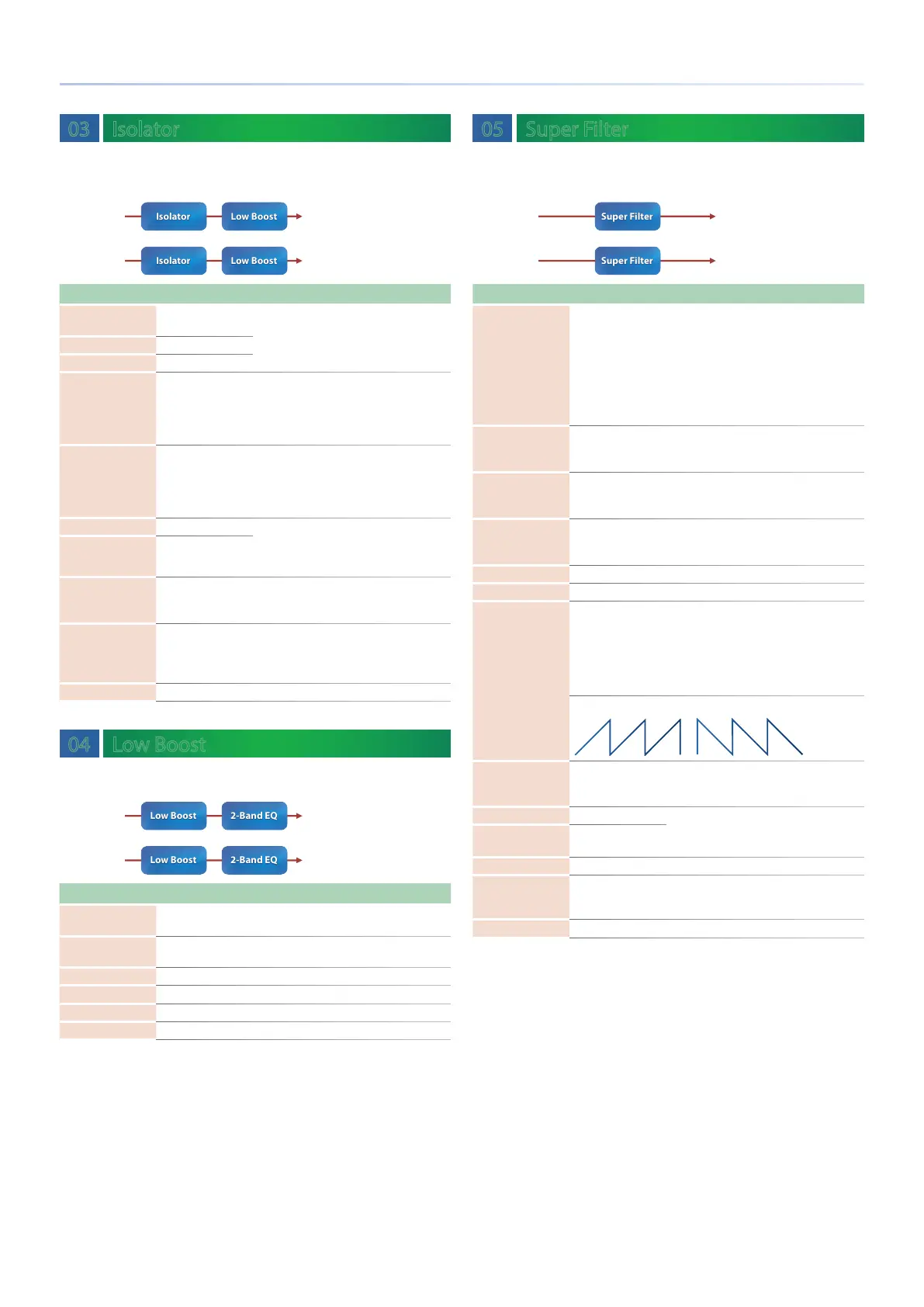
Modulation Wave
TRI, SQR, SIN, SAW1,
SAW2
How the cuto frequency will be modulated
TRI: Triangle wave
SQR: Square wave
SIN: Sine wave
SAW1: Sawtooth wave (upward)
SAW2: Sawtooth wave (downward)
SAW1 SAW2
Rate
(sync sw) OFF, ON
If this is ON, the rate synchronizes with the
tempo of the rhythm.
&
“TEMPO” (p. 52)
Rate (Hz) 0.05–10.00 [Hz]
Frequency of modulation
Rate
(note)
Note
&
“Note” (p. 120)
Depth 0–127 Depth of modulation
Attack 0–127
Speed at which the cuto frequency will
change This is eective if Modulation Wave is
SQR, SAW1, or SAW2.
Level 0–127 Output Level
 Loading...