Rosemount Model 3095 Multivariable Level Controller
A-2
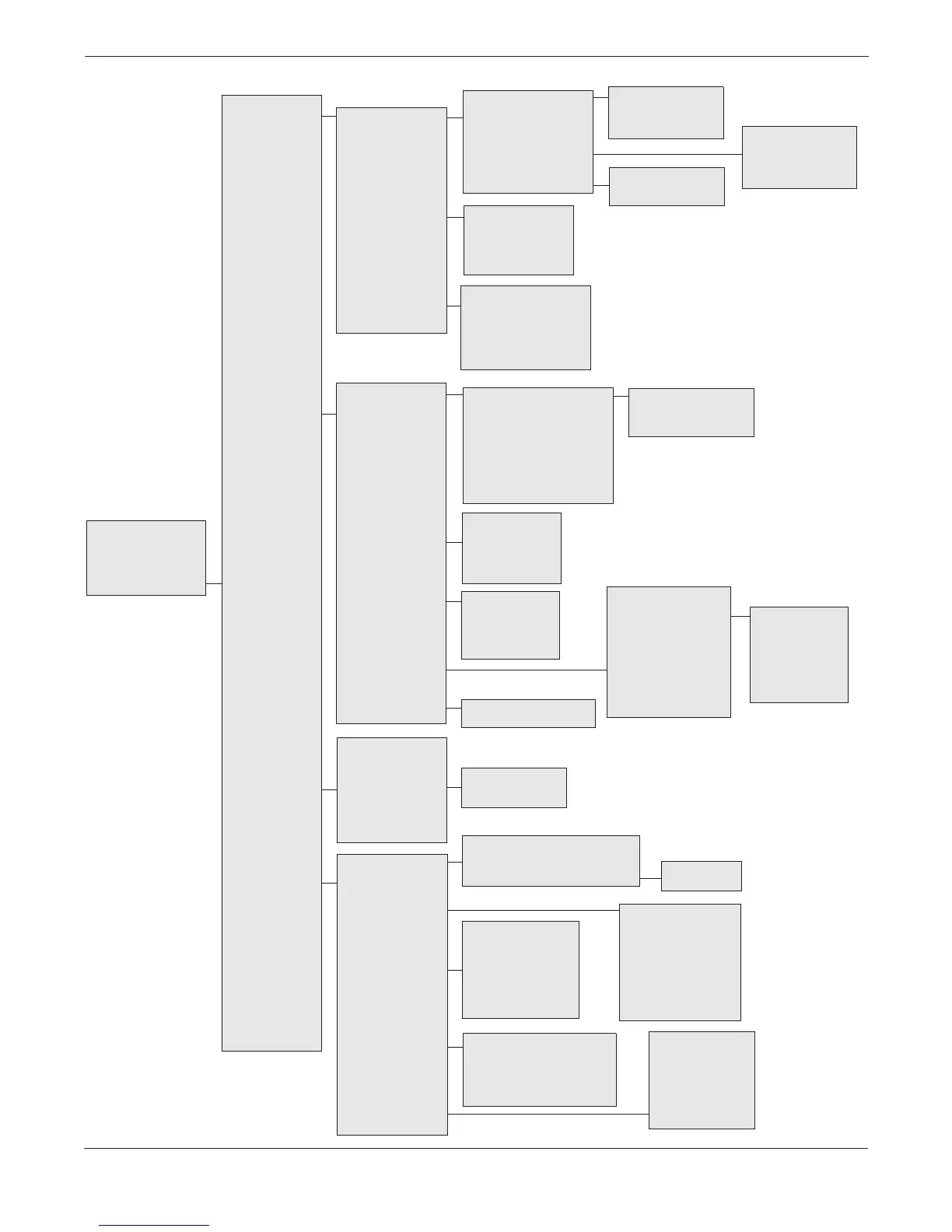
FIGURE A-1. HART Communicator Menu Tree for the Level Controller.
1 CONTROL LOOP
2 SETPOINT
OPTIONS
3 MODE
SUPERVISOR
4 AUTOTUNING
5 MANUAL MODE
SETUP
1 MORE LEVEL SETUP
2 Level
3 Level Unit
4 RANGE VALUES
5 Level Damping
6 LEVEL TRIM
1 Density Unit
2 Density
3 Gravity
4 Transmitter Height
1 Poll Address
2 Number of Request Preambles
3 Number of Response Preambles
4 BURST MODE OPERATION
1 DP
2 DP Unit
3 DP Damping
4 DP Sensor Trim
5 DP USL
6 DP LSL
1 HART OUTPUT
2 CONSTRUCTION
MATERIALS
3 DEVICE
INFORMATION
4 REVISION
NUMBERS
5 LOI
CONFIGURATION
1 Level
2 Setpoint
3 Target Mode
4 Ctl Out / Manual
5 Analog Signal
6 DEVICE SETUP
1 PROCESS
VARIABLES
2 CONTROLLER
3 DIAGNOSTICS/
SERVICE
4 GENERAL
SETUP
5 REVIEW
1 LEVEL
(LV)
2 PRESSURE
(DP)
3 TEMPERATURE
(PT)
1 RTD
2 Process Temp (PT)
3 PT Unit
4 PT Damping
5 PT Sensor Trim
6 PT USL
7 PT LSL
Online Menu
1 D/A Trim
2 Scaled D/A Trim
3 Factory Trim
4 SENSOR TRIM
5 Loop Test
6 View Status
7 Reset
1 Manufacturer
2 Tag
3 Descriptor
4 Message
5 Date
6 Final Assembly No.
7 Write Protect
8 AO Alarm Type
1 Isolator Material
2 Fill Fluid
3 Flange Material
4 Flange Type
5 Drain Vent Material
6 O-Ring Material
7 RS Type
8 RS Fill Fluid
9 RS Isolator Material
– Number of Rmt Seals
1 Control Type
2 Control Action
3 Out HI Limit
4 Out LO Limit
1 MORE CONTROL SETUP
2 P: Gain
3 I: Reset
4 D: Rate
5 Derivitative Filter
6 Bias
7 Balance Time
8 Adaptive Bias Control
9 ABC Static Error
– ABC Stability Threshold
1 Setpoint
2 Setpoint Active
3 Setpoint Rate
4 Setpoint HI Limit
5 Setpoint Lo Limit
6 Setpoint Track
1 Target Mode
2 Actual Mode
3 Shed Action
4 Shed Output
5 Shed Return
6 Power-up Out
1 Control Output / Manual
2 Manual Rate Limit
1 Universal Rev
2 Field Device Rev
3 Software Rev
4 Hardware Rev
5 Sensor Module SW Rev
6 Sensor Module HW Re.
1 Burst Option
2 Burst Mode
1 LV Ttrim
2 DP Sensor Trim
3 PT Sensor Trim
1 Tuning Hi Limit
2 Tuning Lo Limit
3 Alpha
4 Overshoot
5 Time Limit
6 Tune Out Max
7 Tune Out MIn
8 Cycles
1 Tuner
2 Tuning Status
3 AUTO-TUNE SETUP
4 Perform Auto-Tune
5 Accept Auto-Tune
6 Tuning Gain
7 Tuning Reset
8 Tuning Rate
9 Process Gain
– Process Delay
– Tuning Bias
1 Level URV
2 Level LRV
3 Level Unit
4 Level URL
5 Level LRL
1 Meter
2 LOI Enable
3 LOI Display Slot 2
4 LOI Display Slot 3
5 LOI Display Slot 4
6 LOI Level Unit
7 LOI DP Unit
8 LOI PT Unit
1 Display Level Trim
2 Trim Level
3 Level Trim Recall