Hazardous Area Oxymitter 5000
1-6
Instruction Manual
IM-106-350C, Rev 2.2
July 2008
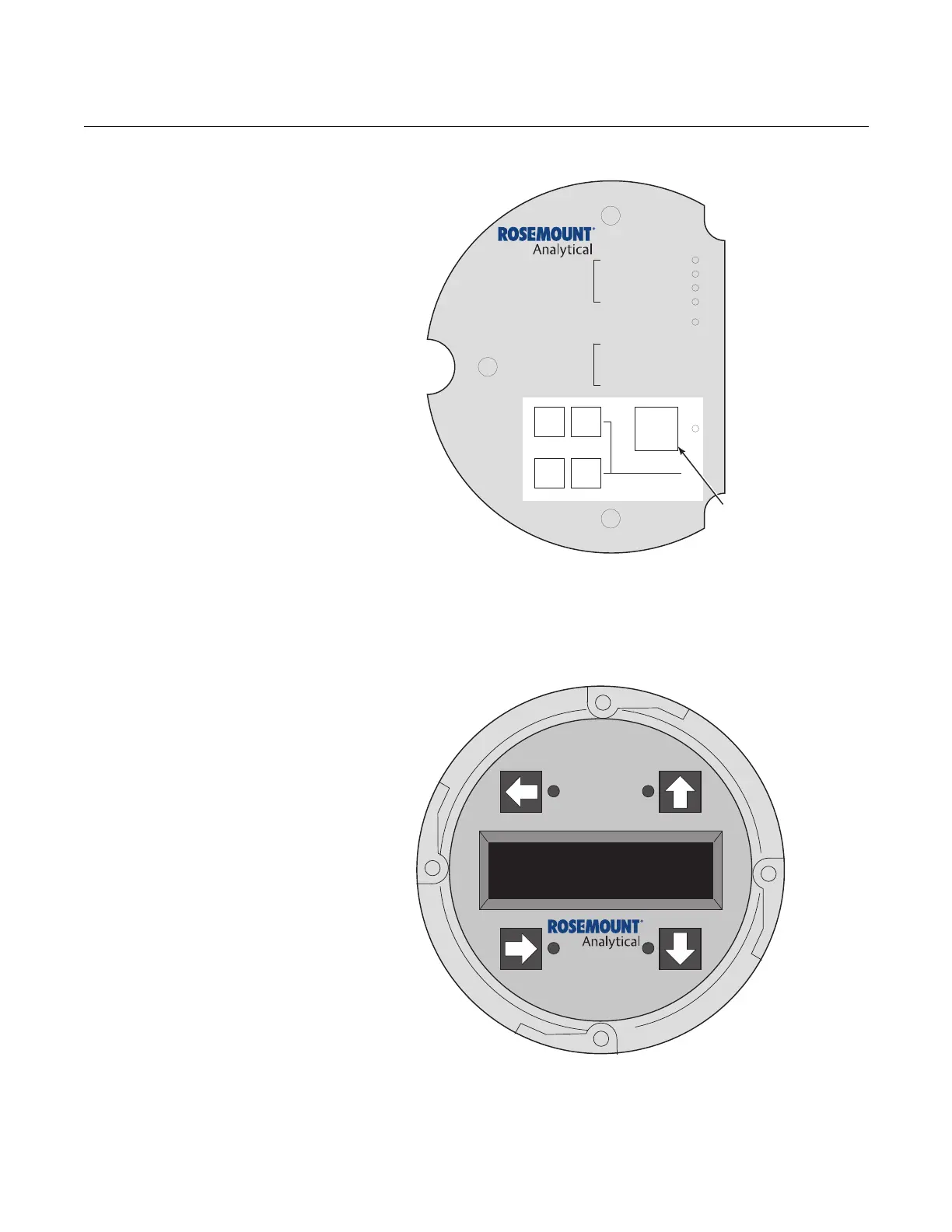
Figure 1-3. Membrane Keypad
3. Membrane keypad, Figure 1-3, and FOUNDATION fieldbus
communication are standard.
Figure 1-4. Local Operator
Interface (LOI)
4. An optional Local Operator Interface Figure 1-4 allows continual O
2
display and full interface capability.
5. Field replaceable cell, heater, thermocouple, diffuser, and PC boards.
DIAGNOSTIC
ALARMS
TEST
POINTS
HEATER T/C
HEATER
02 CELL
CALIBRATION
CALIBRATION RECOMMENDED
02 CELL mV +
02 CELL mv -
HEATER T/C +
HEATER T/C -
INC INC
DEC DEC
HIGH
GAS
LOW
GAS
CAL
TEST GAS +
PROCESS -
% 02
Membrane
Keypad
38740027
 Loading...


