Effectivity: 912 Series
Edition 1 / Rev. 0
d04060
page 125
May 01/2007
BRP-Rotax
INSTALLATION MANUAL
20) Hydraulic governor for constant speed propeller
20.1) Technical data
See Fig. 83
◆ NOTE: See therefore also SB-912-052 "Installation / Use of governors
for Rotax engine type 912 and 914", latest issue.
- drive via prop gear
- location of the necessary connection on the crankcase:
see Fig. 83
- connections
mounting pad: AND20010
thread size: M8
Effective thread length: max. 14 mm (0.55 in.)
toothing: internal spline 20/40 SMS 1834 NA 14x1.27x30x12
direction of rotation of governor drive: clockwise, looking at mounting pad
- power input: max. 600 W
- operating pressure: max. 30 bar (435 psi.)
■ CAUTION: Pay attention to manufacturer's specifications.
◆ NOTE: Speed reduction from crankshaft to hydraulic governor is
1,724 or 1,842, i.e. the vacuum pump runs with 0,58 or 0,54 of
engine speed.
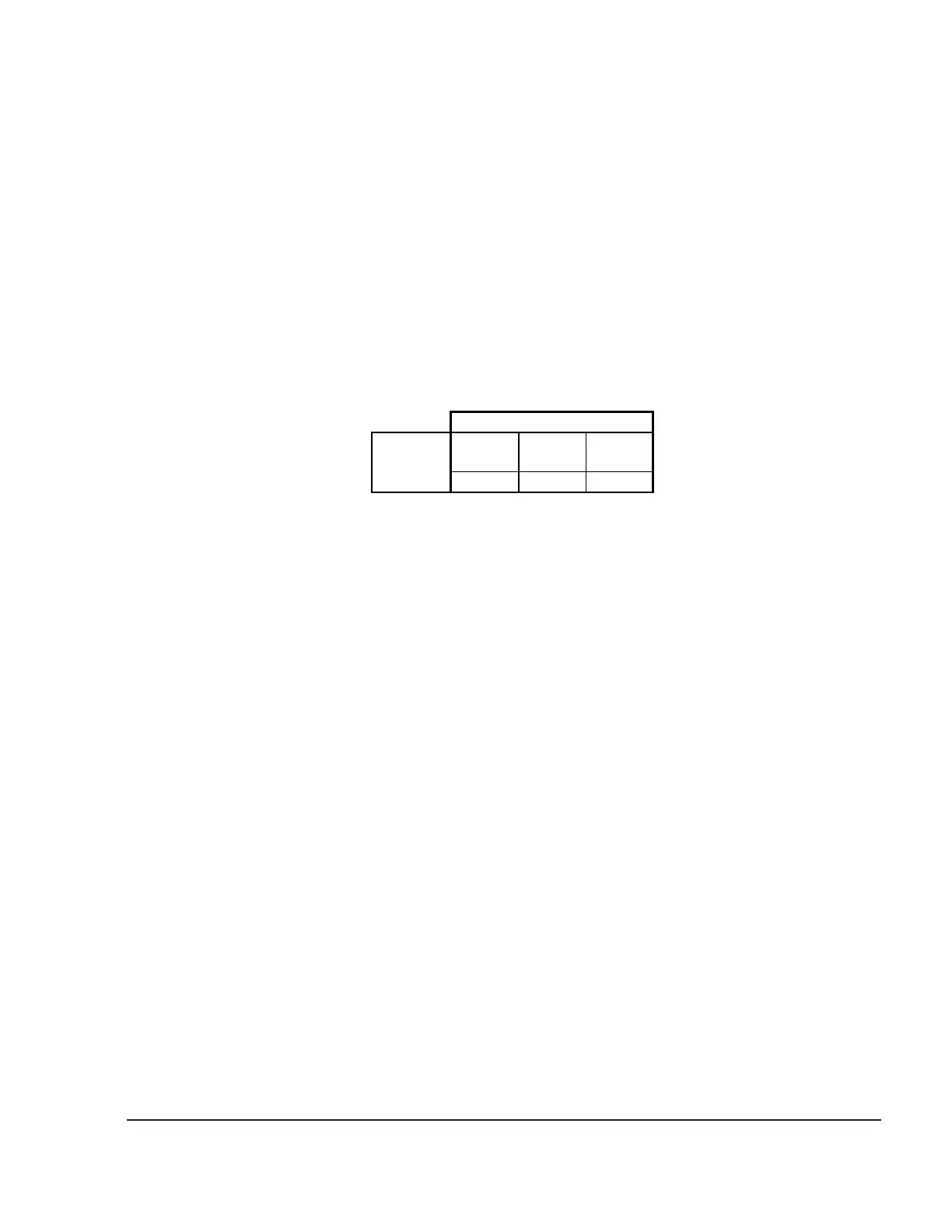
x axis
mm
y axis
mm
z axis
mm
-206,3 0 51,5
connection
coordinates
09191

 Loading...


