Page 47 of 82 Revision No.: 1.5
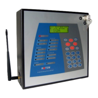
11) Installation
1. Plug in the Communicator to a power source.
2. Go to 'Hardware Profile' selection, by choosing menu 9.1 in the main
menu (see Fig. 3). Fig. 83 results this choice. Make sure all the
components are recognized by the Communicator
.
Fig. 83: Hardware Profile menu screenshot
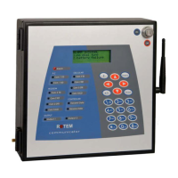
3. Go to 'Battery Test' option, by selecting menu 9.3 (see Fig. 3). Fig. 84
results this selection. Check the battery recognition and charging; as
long as the communicator unit is plugged in, the charger inactive note
will be displayed.
Fig. 84: Battery Test selection screenshot
4. Fig. 85 presents the functional block diagram of the controller.
5. Connect controllers according to the photos below; If RF
communication is used connect the controllers according to Fig. 86-87.
6. Install the communication software from the attached CD (for
installation instructions, please refer to Appendix D).
7. In order to install the external connection box, refer to Fig. 88.
Attention!
• Do not keep the battery connected without electricity.
• Use an exclusive phone line for the Communicator. (Do not share a
line for the Communicator with another phone)
Note: Sometimes using a phone line via private switchboard might
cause problems, therefore it is recommended to use a different line to
the communicator.