Platinum Plus
67
that must be turned off from time to
time, assign them as ‘same as #’ relay
codes, and chose the ones that work all
the time as the reference relays.
e. The ‘same as #’ codes do not add to the
device count on the main display active
section. If you duplicate ’33 Tun.Fan 1’
(tunnel fan 1) several times, all those
relays work together but the tunnel fan
count in the ACTIVE section of the
main display will increment by 1 when
tunnel fan 1 turns on.
f. To avoid scrolling
a long way to get to
higher numbered relay functions, enter
the two digit code directly while in the
pop-up that lists the choices. To get to
100 and higher, press the +/- key first,
then the two least significant digits.
2. Standard Mode Only:
Apply check marks
in the Min, Nat and Tun columns to indicate
in which ventilation modes, Minimum,
Natural or Tunnel, the functions need to
work. To add a check mark, place the
cursor, then press the +/- key. To remove a
check mark, press the +/- key again.
3. The Platinum Plus shows the type of relay
the cursor is on at the bottom left of the
screen. N.O. Relay stands for Normally
Open Relay and N.C. Relay stands for
Normally Closed Relay. Usually the relays
will be of the normally open type.
4. Help | Set Parameters:
a. You can choose to operate the relays
under AC power to reduce heat, or
under DC for full power operation.
Factory default is AC or reduced heat.
b. You have the option of reversing up to
5 of the relays. The term N.C. Relay
means it converts the function of a
standard normally open relay to
normally closed. The relay will be
reversed under normal operation so that
it is On when it would normally be Off
and vice versa. This does not affect the
operation of the On/Off portion of the
ON/Off/Auto switches. It only affects
the function in Automatic mode.
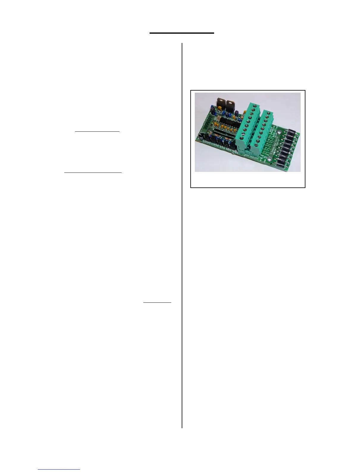
Analog Sensors
Each Platinum Plus has one analog
input card. This card accepts up to eleven
sensors. Position eleven is reserved for future
use. Positions 1 through 8 can be used for
temperature sensors only; positions 9 and 10 are
dedicated to humidity sensors.
The card has two connectors. The lower
one takes odd numbered temperature sensors, the
upper one the even numbered ones. The left two
terminals on each connector are ‘Common.’
Each sensor must have one lead connected here.
The other lead connects to one of the positions
marked T1 through T8. Each sensor should have
a shield wire connected to the common
grounding bus bar mounted just below the cards.
One humidity sensor connects to the lower
connector to the terminals marked White, Red
and Black. A 2
nd
humidity sensor shares the Red
and Black terminals, but connects its white wire
to the upper row connector labeled T9. The Wind
Direction terminals labeled green and yellow are
for future use.
There are 5 jumpers along the left edge
of the board. The upper 4 should be in the TMP
position to read temperature; the lowest one
should be in the HUM position. The other
positions are for future use.
You can assign a sensor for Circuit
Breaker temperature monitoring. This sensor will
normally be placed directly on the main circuit
breaker for the facility, and set to alarm in the
Management Menu | Alarm Setting at
temperatures near 135ºF. Circuit breakers often
become warmer than usual prior to failing. This
sensor can warn of impending failure to allow
changing the breaker before failure.
Analog Input Card, C-PP-RAIC-11