reservoir from boiler circuit CH (starting P2
pump).
Night cooling- Yes enables/ NO disables night
cooling mode in hours 0
00
÷5
00
.
Night cooling ON – DHW reservoir temperature
(T2 sensor), when exceeded at 0
00
if night
cooling function is enabled, the controller will
decide on night cooling activation.
Night cooling OFF – DHW reservoir
temperature (T2 sensor), to which the
controller will be cooling down the reservoir
(if night cooling function is enabled and if in
hours 0
00
÷5
00
Night cooling ON
temperature is exceeded).
Alarm TCOLcr – Switching on (YES) or off (NO)
the alarm on exceeding TCOLcr
temperature. This function will not affect the
controller operation. If the parameter is set
as NO, the controller will not alarm when
TCOLcr temperature is exceeded at the
collector sensor.
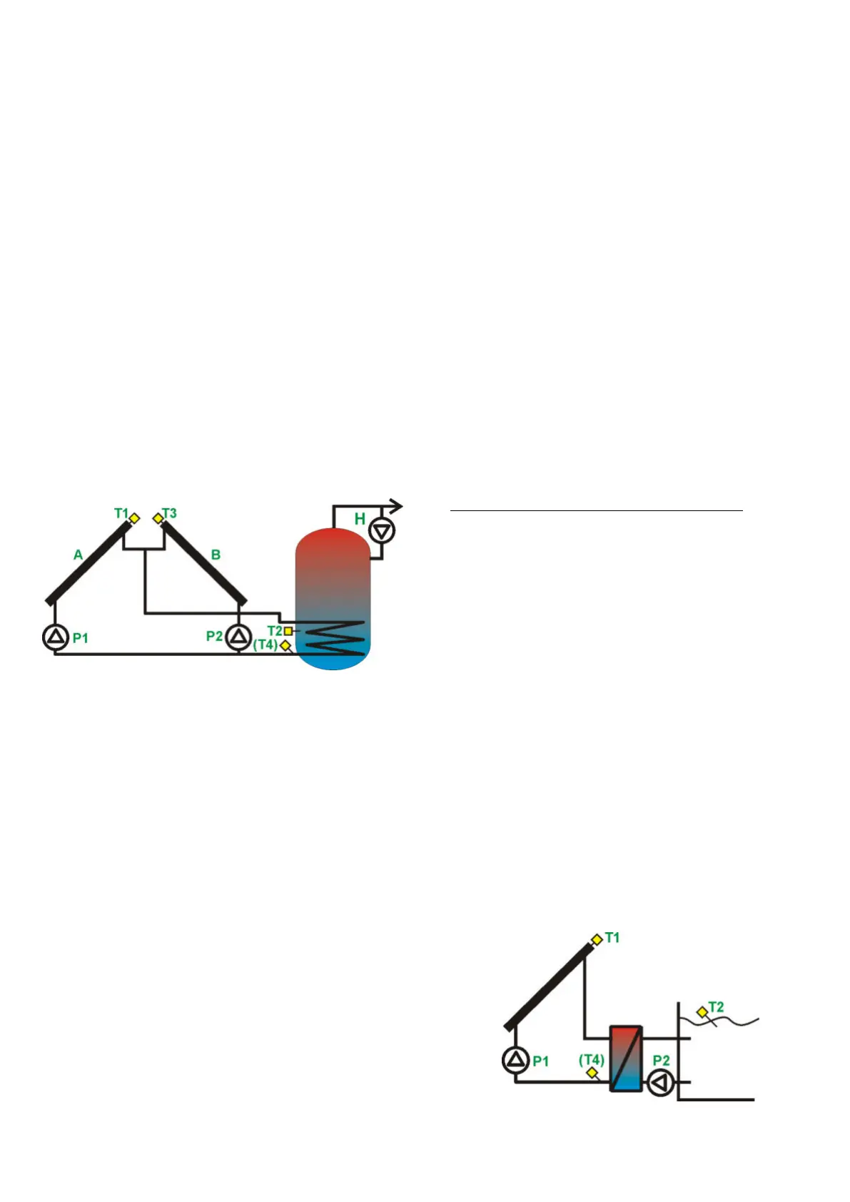
13.9. Solar thermal scheme H
Loading of DHW reservoir with two collector sets
oriented toward two directions.
Fig. 13.8 Solar thermal scheme H
The collector pump P1 of collector A will
be started at 100% capacity, if the difference
between T1 and T2 exceeds the value of
dTonDHW and it will be working for the time
specified in parameter tP. If after this time the
difference between T1 and T2 is still above
dTonDHW, the pump speed will remain at
100%. If the said difference between T1 and T2
drops below dTonDHW, the controller will start
reducing the pump speed, until the difference
between T1 and T2 reaches the value specified
as dToffDHW. If the difference between T1 and
T2 is between the values dTonDHW ÷
dToffDHW, the controller will calculate and set
the pump speed proportionally. When dToffDHW
is reached, the pump will work at minimal speed
(Pmin), below it will be stopped.
The collector pump P2 of collector B will
be started at 100% capacity, if the difference
between T3 and T2 exceeds the value of
dTonDHW and it will be working for the time
specified in parameter tP. If after this time the
difference T3 and T2 is still above dTonDHW,
the pump speed will remain at 100%. If the said
difference between T3 and T2 drops below
dTonDHW, the controller will start reducing the
pump speed, until the difference between T3 and
T2 reaches the value specified as dToffDHW. If
the difference between T3 and T2 is between the
values dTonDHW ÷ dToffDHW, the controller
will calculate and set the pump speed
proportionally. When dToffDHW is reached, the
pump will work at minimal speed (Pmin), below
it will be stopped.
The system will work, until T2 sensor
reaches TsDHW preset, then collector pumps P1
and P2 are stopped.
If T1 or T3 collector temperature reaches
critical value (TCOLcr), then the controller will
allow switching on pump P1 or P2 (depending
which collector has critical temperature) in order
to reduce the collector temperature below
hysteresis HP1 for P1 and HP2 for P2.
If the reservoir temperature at T2 sensor
reaches the value of TDHWmax, the controller,
despite of critical collector temperature
(TCOLcr), will stop the collector pumps,
disabling the collector cooling. It is to protect the
reservoir from overheating.
List of parameters in Adjustment menu
TsDHW- Reservoir temperature preset
Night cooling- YES enables/ NO disables night
cooling mode in hours 0
00
÷5
00
.
Night cooling ON – DHW reservoir temperature
(T2 sensor), when exceeded at
0
00
if night cooling function is enabled, the
controller will decide on night cooling
activation.
Night cooling OFF – DHW reservoir
temperature (T2 sensor), to which the
controller will be cooling down the reservoir
(if night cooling function is enabled and if in
hours 0
00
÷5
00
Night cooling ON
temperature is exceeded).
Alarm TCOLcr – Switching on (YES) or off (NO)
the alarm on exceeding TCOLcr
temperature. This function will not affect the
controller operation. If the parameter is set
as NO the controller will not alarm after
TCOLcr is exceeded for the collector sensors
T1 and T3.
13.10. Solar thermal scheme I
Loading of pool system.
Fig. 13.9 Solar thermal scheme I


 To Next Page