tP – Minimal time of the collector pump work. If
the difference between collector and
reservoir temperatures drops to dTon, the
collector pump will be started for the time of
tP.
HP1- auxiliary hysteresis for P1 output.
HP2 - auxiliary hysteresis for P2 output.
Too high values of HP1, HP2 settings
may lead to large temperature
oscillations in the system, so it is
recommended to leave them at the level
of 1°C.
tVALVE – minimal operation time of the
controller’s valve that switches the circuits
(used in solar application F).
tDLY – time of delay for switching on/off the
pump downstream heat exchanger.
TCOmin – minimal temperature in CH circuit
(measured by T4 sensor) in scheme G,
which allows loading of DHW reservoir from
the boiler system. Below this temperature
(even if there are conditions for reservoir
loading, i.e. TsDHW is lower than preset or
dTCO is reached), the controller will disable
the reservoir loading. This prevents CH
circuit operation below the boiler’s dew point.
dTP2 – temperature difference between T1
collector and T4 exchanger, if reached the
controller will start exchanger pump in
scheme I. Operation with tDLY is also
possible, then dTP2 setting must set as
OFF. At such setting, the controller will run
P2 operational algorithm with delay of tDLY
in relation to P1 pump operation. Alarm from
T4 sensor will not be reported.
19.2. I\O Options\Configuration
Depending on the length of sensor extension
cable, sensors will show temperature without
taking into account resistance of connection
lines. To compensate cable effects, it is required
to perform sensor compensation procedure.
19.2.1. Wire length compensation
It consists in measurement of wires
connected to a sensor (measurement track),
reading value from the compensation table for
connecting wire resistance, and programming
this value in the controller.
The controller will automatically move sensor’s
characteristics to compensate the effect of
additional resistance.
When you enter menu, the controller
displays current values of temperature
corrections.
If the controller displays 0.0, it means that no
correction has been introduced for given track.
To clear any compensation data for the track,
enter 0.0 value.
The procedure may be conducted using
ohmmeter to measure resistance of both cable
conductors and selecting from the table
respective value for measured resistance.
If received result indicates correction above 2°C,
it may means that the cable have resistance
bigger than permissible or that they are too long.
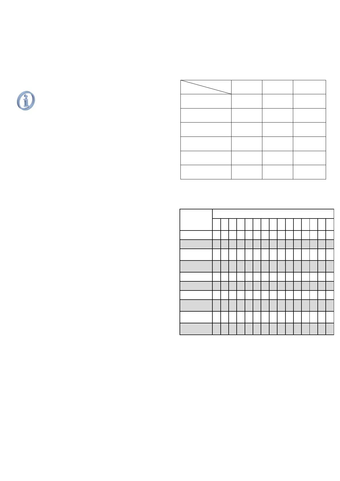
Table of cable lengths and resistance.
19.3. Options\Functions
Depending on scheme and version, the following
settings are available in the Functions menu:
* parameter available in the menu only when set
parameter Work fluid = 0.
Antifreeze – setting ON enables the antifreeze
function. The collector pump will be started,
if the solar work fluid temperature drops to
the freezing value set for the work fluid. For
correct operation of this function, it is
required to select suitable solar work fluid.
Collector pump will be stopped, if the work
fluid temperature rises by 2°C. When the
function is off, the controller will not monitor
antifreeze and it may lead to damage of the
solar system in winter period, so it is
recommended that it remains on. In scheme
E, antifreeze function operates in the circuit
of container A, in scheme F the function