controller will be cooling down the reservoir
(if night cooling function is enabled and if in
hours 0
00
÷5
00
Night cooling ON
temperature is exceeded).
Alarm TCOLcr – Switching on (YES) or off (NO)
the alarm on exceeding TCOLcr. This
function will not affect the controller
operation. If the parameter is set as NO, the
controller will not alarm after exceeding
TCOLcr for the collector sensor T1.
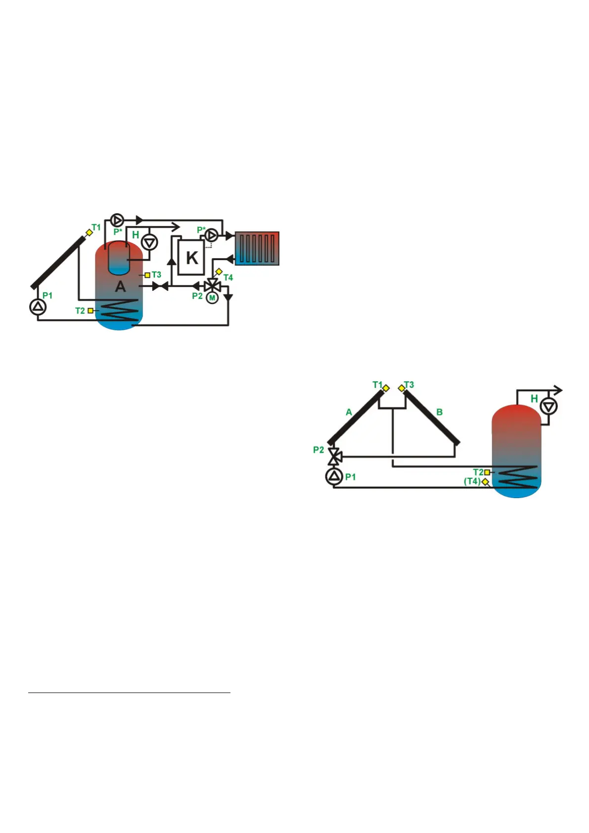
13.12. Solar thermal scheme K
Loading A container-in-container type buffer with
low-temperature CH system assist.
Fig. 13.11 Solar thermal scheme K
Collector pump will be activated with
100% power, when T1-T2 difference exceeds
dTwlDHW value and will operate for tP
parameter time. If after this time T1 and T2 is
still higher than dTwlDHW, then the pump will
still operate at the highest output. If the
aforementioned difference falls below dTwlDHW
value, the regulator will start to gradually
decrease pump output, until the difference
reaches dTwyDHW value. When T1 and T2
difference is between dTwlDHW ÷ dTwyDHW
values, the regulator will measure and adjust the
output in a proportional manner.
When dTwyDHW value is reached, the pump
operates at its minimum output (Pmin
parameter). Any value below will cause it to
stop.
If temperature difference dTAB (T3 and
T4 difference) between A buffer (T3 sensor) and
CO system return (T4 sensor) is not reached,
P2 output (a valve controlling return from
system) will redirect return water to buffer’s
center. If T3 temperature increases above
T4+dTAB, three-way system valve will be
switched in buffer’s bottom direction, and K
boiler will be powered by water from boiler’s
center.
List of parameters in Adjustment menu
TzDHW – Preset container’s temperature A and
B.
dTAB- temperature difference between A buffer
and system return (on T3 and T4 sensors),
after which the regulator switches three-way
valve. P2 is enabled, when dTAB difference
(between T3 and T4 temperatures) falls by
auxiliary hysteresis AH2.
Night cooling – YES enables / NO disables
night cooling mode between 0
00
÷5
00
hours.
Cooling temp ON. – DHW container
temperature (on T2 sensor), if exceeded,
and night cooling is enabled, the regulator
will begin the cool down at 0 AM.
Cooling temp. OFF – DHW container
temperature (on T2 sensor) to which the
regulator will be cooling down the container
(if night cooling function is enabled and
Cooling temp. ON temperature is exceeded
between 0
00
÷5
00
).
TCOLkr alarm – Enabling (YES) or disabling
(NO) of the alarm of exceeding TCOLkr
temperature. This function does not influence
regulator’s operation. If the parameter is set
to NO, the regulator will not set off an alarm
after exceeding TCOLkr collector’s
temperature.
13.13. Solar thermal scheme L
DHW tank is loaded by two solar collector
sets oriented towards two points of compass
using one pump group and collector circuit
separating valve.
Fig. 13.12 Solar thermal scheme L
Regulator selects the solar collector of
higher temperature to operate. Solar collector
serving pump is activated with 100% capacity
once the difference of T1 or T3 (subject to the
solar collector selected) and T2 has exceeded the
value of dTonDHW. The pump will work over the
time set in tP. P2 valve is set at the position
appropriate to switch the system into selected
solar collector. If, upon elapsing of this time, the
difference of T1 or T3 and T2 is still in excess of
dTonDHW value, the pump rpm value will
remain set at 100% all the time. Once the
difference between T1 or T3 and T2 has dropped
below dTonDHW value, regulator starts reducing
pump rotary speed until the difference of T1 or
T3 and T2 has reached the value set in
dToffDHW. In case the difference of T1 or T3
and T2 falls within the range from dTonDHW to
dToffDHW, the regulator computes and sets the
rpm value proportionally.
Once the difference of T1 or T3 and T2
has reached the value set in dToffDHW, the